At the time of designing the house, the end result that we get is a working drawing, and usually also comes with 3-dimensional design, mockups, or other completeness. Particularly for working drawings we recognize several types of images contained in this document including visible drawings, pieces, construction details, electrical installation plans or plotting of electrical equipment, sanitation plans, and detail in buildings such as visible detail as well as construction details, such as foundation , columns and structures down to the detail of each frame along with the placement of the frame
With the image of this document we will get a good guide in building a house. If there is no picture of this document, the house will usually be built in a careless and improper manner so that it is not planned in terms of both construction and aesthetics. Working drawing documents are also required for the management of IMB requested by the local government in addition to working drawings can also be used when you apply for a home renovation loan to the bank.
We can get working drawings through several parties including architects, civilian experts or even draftsmen or equals with more capabilities. The fact is that actually everyone can make work drawings, but the most important thing is not just work drawings, but the results of the work drawings. What is meant by the results of work drawings is how buildings when realized in reality. The design element is very important in this regard. In general we cannot submit a design to people who are not experts in the sense of not architects because architects are people who are trained and specifically to create design images with a high enough aesthetic. Besides that, although there are many architects available, not all architects can provide what you want completely. There may not even be an architect who is able to understand exactly what you want, but actually who has a lot of knowledge to make a design work.
Returning to the working drawing document, the following is an explanation of each image that is usually in a working image.
Drawings
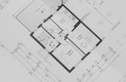
The floor plan shows the size and space of the space to be built in a house. This drawing includes in addition to space laying, also usually containing where the placement of water-related or sanitary equipment such as the location of the kitchen, toilet and washbasin. Sometimes the architect gives a column plan image where there is a column point that can be seen in the floor plan. But there are also architects who do not provide plans for the placement of columns in the drawings. This is because the policy of every architect is different in the sense of architectural drawings must sometimes be translated by civilian experts in the laying of column columns in the floor plan. If the architect provides a plan for placement of columns in the floor plan usually architects have considered the construction factor in the drawings.The floor plan shows the size and space of the space to be built in a house. This drawing includes in addition to space laying, also usually containing where the placement of water-related or sanitary equipment such as the location of the kitchen, toilet and washbasin. Sometimes the architect gives a column plan image where there is a column point that can be seen in the floor plan. But there are also architects who do not provide plans for the placement of columns in the drawings. This is because the policy of every architect is different in the sense of architectural drawings must sometimes be translated by civilian experts in the laying of column columns in the floor plan. If the architect provides a plan for placement of columns in the floor plan usually architects have considered the construction factor in the drawings.
Draw pieces
This image is a slice or piece of a building that can show many things such as floor height, roof height, and building materials used like roofing material. The cut image usually includes the size of the inter-wall seen in the piece and the height of many elements in the piece. Important pieces of drawing for contractors or craftsmen working on the ground to know many aspects of buildings built like ceiling height.
Image appears
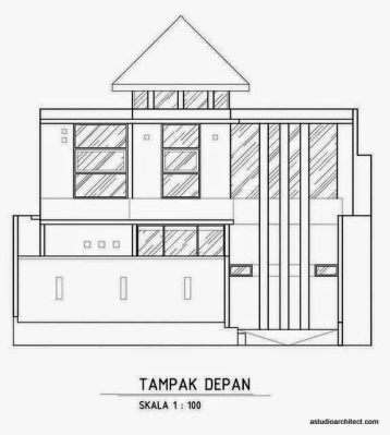
The picture shows how the building looks in 2-dimensional form. This image usually contains a global measure of size from the height of the building. This is useful for a contractor or handyman guide who will estimate a certain height heights of some elements in the building view in 2-dimensional form. The picture also contains several elements such as the location of the window and the frame and ventilation.
Picture of the foundation plan
![image.png]
(https://ipfs.busy.org/ipfs/QmQigB37J5pw5GVghjJjrWb8hde9kMHPhFqYheZ7BQfSjm)
This image shows how the foundation is formed beneath the building. The place usually contains a picture of a continuous foundation and a footprint foundation for conventional residential construction. This picture shows the relationship between the column and the construction of the foundation below so we can see how the relationship between this column continues the force to the ground. The foundation plan is also usually equipped with a foundation detail to see the size of the foundation used. Moreover the drawing of the foundation plan should also be supplemented by structural calculations for the foundation. Structure calculations are carried out by structural experts or experienced civilian experts. While architects sometimes do not provide structural calculations for the foundation.
Draw a draft plan
A drilling plan is required to design a 2-storey or more house where this picture contains a placement plan and beam size on the 2nd floor of 3rd floor and so on. If the building is only floor 1 usually do not have to be equipped with the draft plan is okay because for conventional construction usually only required a ring beam at the top of the wall. The draft plan drawing covers the height of the concrete and also the size of each beam. Civilians usually play a role in determining this drafting plan in addition to that sometimes architects also provide this image when experienced or supported by civilian experts.
The picture looks up and the roof plan
This image is an image to show the shape and construction of the roof. The top view shows a 2-dimensional image from the roof so it looks part of it where sometimes it is also equipped with the roof material. The roof plan image is a more detailed picture covering the part of the roof like a horse frame and also the roof coverings.
Pictures of electrical installations or plans for placement of electrical equipment
The difference between the electrical installation drawings and the plan for the placement of electrical equipment is that the electrical installation is usually made by a civilian expert while the drawing of the electrical equipment is made by the architect. These two images are different in terms of completeness where the electrical installation image is much more detailed than the electrical equipment maintenance plan drawings. Both of them together show the placement of various electrical equipment in the floor plan which is usually equipped with standard height and special height of each electrical equipment. For conventional home work drawings, it usually doesn't need to be complicated. Buildings on 3 floors that must be planned by electrical mechanical experts.
Image sanitation plan
![image.png]
(https://ipfs.busy.org/ipfs/QmPe1EHYpT6aYX4p5hyH7fsZtMkiyzsbH742auRhwuLVGy)
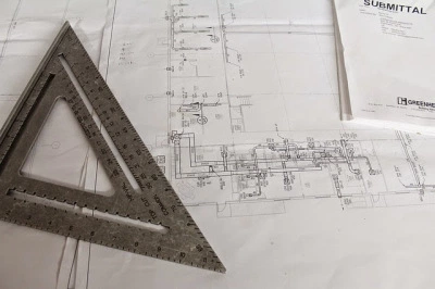
The sanitation plan drawings include many sanitation related equipment such as septic tanks, wells and absorption wells, as well as covering the lower and upper tank plates and how the pipelines are piped in clean water pipes, dirty water or stream flow. This includes how the flow of clean or clean water is distinguished from the flow of dirty water or black and gray water. Blackwater is the flow of sludge from the WC to the septictank. While gray water is the flow of dirty water coming from channels such as kitchen sinks or used water from the bathroom. Aside from the pipeline, the sanitation plan also includes the location of sanitary equipment such as wash basins, toilet and afur (water hole in the bathroom).
Drawing frames and frame details
A good design is always equipped with a picture of the jamb and sill jumble because the drawing will determine how the shape of the doors and windows and the vents to fit the design and build the previously thought place. The drawing of the frame shows the location of each frame determined by the code code that represents each frame, so there are no frames that are altered or different in shape from the original design. The details of the frame contain images of each frame that is very detailed with its size so as to indicate the thickness of the frame and window as well as parts of wood or aluminum glass.
Why should there be a work picture?
In some cases, house houses must be designed and equipped with work drawings complete with structural drawings and construction, especially if designed by architects so that construction work goes exactly as planned. This particular drawing of a structural structure must be made by an experienced structuralist or skilled civilian who can calculate the loading of each column and beam and other elemental elements such as steel quantities and all structural or force-loaded components. This is usually common for buildings that are not simple or buildings on 3 floors where buildings like this are usually required to have construction or structure drawing documents. Of course the construction drawings must also be completed with the calculation of loading.
In addition to the above-mentioned technical document documents there is also a document that complements the working drawing documents submitted as IMB and as a guide for development or implementation in the field. This drawing drawing includes a 3-dimensional image of how the estimate of the building after it is built, to show the shape and also the lighting effects that will exist in a building after it is built. 3-dimensional images can also typically include interior design drawings in three-dimensional shapes where the interior design of a home or other building has been constructed to show how the inside of a building is looking good or not.
No less important than all the documents is the building budget plan document or RAB. This budget plan document is a calculation of the cost of building a house or other building that is tailored to the finished design drawings. Shows down to the detail of material and development price of each element such as concrete work, wall work, finishing work.
Not simple
All of these documents can be produced in the services provided by your Architect. Surely this image drawing document is not a simple job because it covers all planning and results. Sometimes if you rent one of the parties whether the architect or the contractor usually the party still requires the other party to help the completion of the design. For example, if you hire an architect, usually the architect needs a civilian expert. Likewise, if you hire a civilian expert, you will usually need an architect to design. This is usually common in Indonesia. Your stay determines whether you will hire an architect or a civilian to start your design. The best course is to hire the services of an architect first to plan how the construction you are going to build because civilians are not experts designing. Likewise when you build, there must be a supervisor architect


Thank you for dedicating your time and attention to the STEEM Network.
We took some time to gather some statistics about your posts, we hope you will find them interesting.
Average Votes Per Post: 3
Average Replies Per Post: 0.2
Average Post Word count: 698
Follow us for future benefits. Why not delegate some STEEM Power 1SP, 5SP, 10SP, 100SP, or Donate to Help Support
Warm Regards,
We can also resteem and upvote more of your postsWe Love You @juanibra, and Everything You Do.@WeLoveYou.
Learn More, Read Our Introduction
If your reputation is lower than 30 resteeming with @WeLoveYou only costs 0.001 SBD