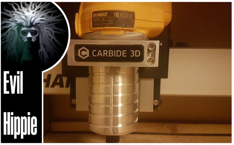
And so the journey can continue. My spindle/router arrived two days after the cnc-frame and so I could get on with doing my first job.
The very first job could have been done without the spindle since the tradition is to mount a feltpen and use the shapeoko as a very slow and expensive printer.
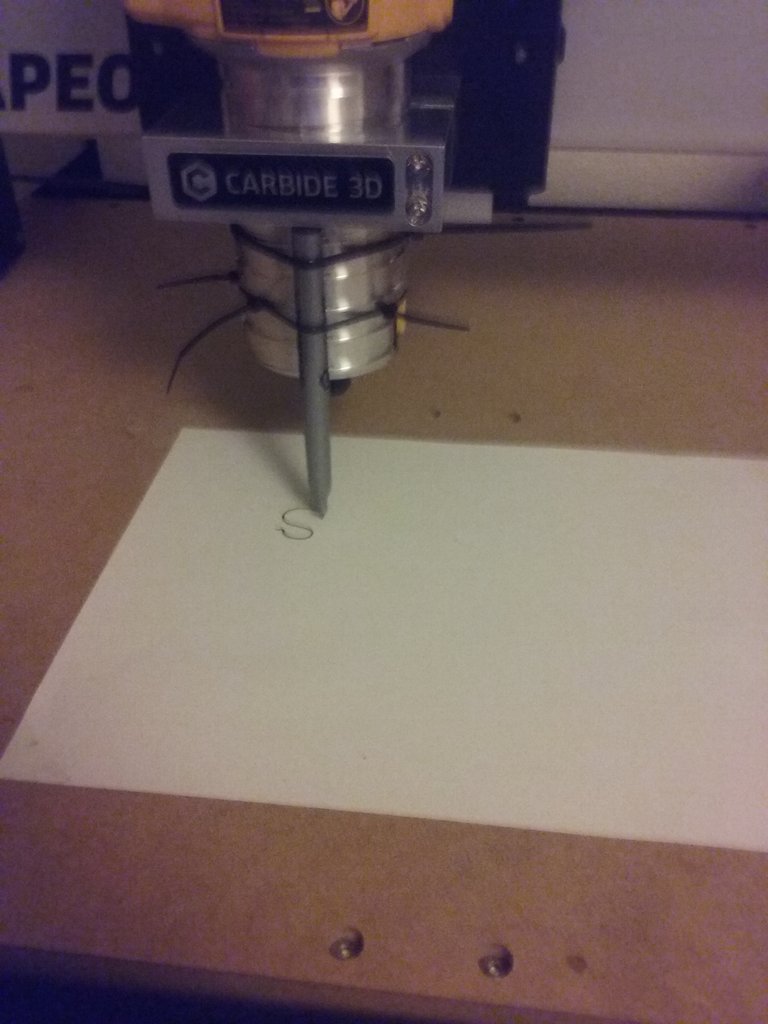
I could not find a good way to secure the pen directly to the holder so i chose to wait (it might have been a factor that I didn't have time as well)
I got a video of the world-changing event here:
After that I decided to go ahead and do my first actual carving operation and to stay on the safe side I did a very simple setup.
I started up carbide create which is a 2.5D cad/cam program that is freely available and exports gcode directly. The simplest, yet still interesting thing I could think of was to write my company name in inkscape and do what is called a v-carve of that in foam.
v-carving is when you use a v-shaped carver and the cnc-mill controls the width of your design by plunging the bit deeper into the material.
I chose it because it is easy to setup and still has a fairly nice result.
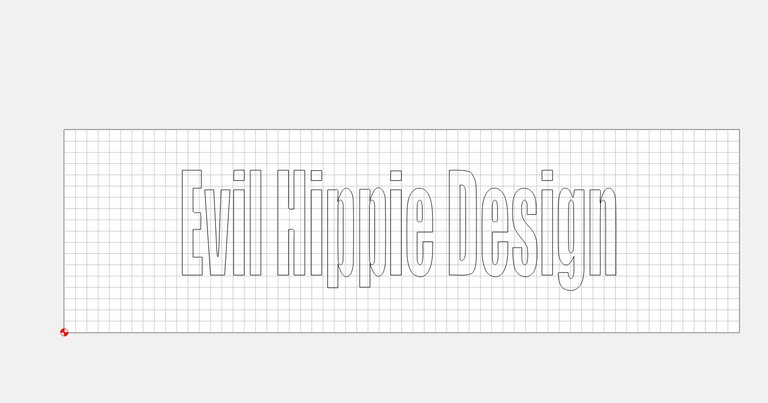
this is what it looks like after importing an svg file made in inkscape into carbide-create.
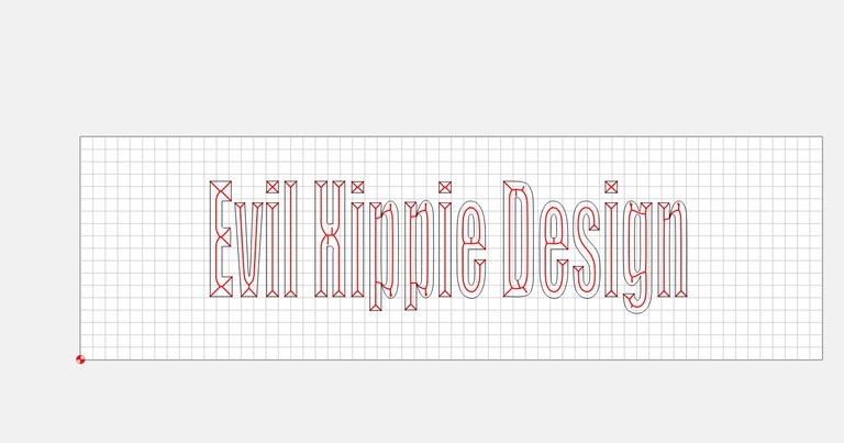
and this is what it looks like with the actual path drawn. You cannot see the width here but it is all fixed automatically so thats very nice.
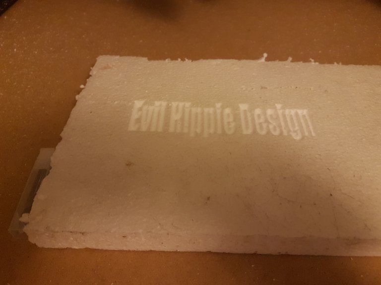
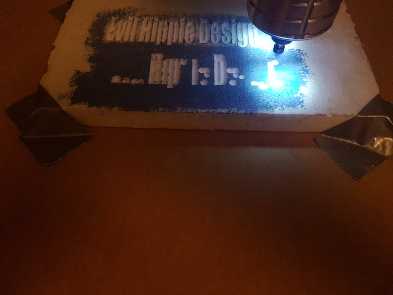
I put a piece of foam board in there with doublesided tape , zeroed the mill (always remember to zero the mill) and let loose
Zeroing the mill means you manually jog the router so that the bit is situated over what is origo on your cad drawing. In this case I chose the lower left corner (denoted by the little red checkered circle in the corner) the mill will run relative to that point whether there is material or something else, until its limits so stuff can go catastrophically wrong if you are not careful.
BTW you need to zero the z-axis as well and again if you have miscalculated the thickness of your material the bit will dig into the bottom of the mill. Thats why the plate in the bottom is called a wasteboard and is made from easily replaceable mdf plate.
Well as you can see i managed to not destroy anything and I got a nice result. I made two versions because it was kind of hard to see the result in the white foam so I did another where I painted the surface first. it helped a little but not alot.
next on my todo list was to buy some proper router bits and some collets to hold them, also I needed to find a software that supported real 3d milling. Otherwise I wouldnt be able to do all the projects I had bought it for in the first place.
Whether I succeded in this must wait until another post. Now i need to go make some food for my family. Until then, cheers.

Im EvilHippie, a compulsive creative and jack o' trades. If you want to know more about me, check out my introduction post here
If you like what you see, feel free to upvote, follow and resteem
or you can check out my accounts on these sites:
Your'e welcome to like or follow me there as well.
This is so cool ! The results are really neat and I love the video of it writing ShapeOko so nicely !
Thanks, it is almost magical to watch, even though it is just printing, and even doing it in a very ineffective way.
Cool! This poor foam board didn't stand a chance! Total overkill :)
About that software finding software part... What do you mean "real 3d milling"? Have you tried Fusion 360 CAM? IMHO it is as "real 3d milling" as it gets...
alot of the programs I have seen are 2.5D in the sense that you cannot take e.g. a basrelief and do a path of that. fusion 360 does that and more and it might still become the one I choose. i want to try out some different options first though as I am an accomplished blender user so i really dont need all the fancy modelling that comes with fusion 360. i only need a good toolpath planner. Freecad is fairly nice as well but needs Opencamlib installed to be able to do 3d toolpaths
I would like to clarify... What I meant to say is that you can import some arbitrary STL into Fusion 360 and generate your gcode. Fusion can generate parallel toolpaths just fine and you don't even have to convert your STL to BRep. It easily produces toolpaths with smoothly varying Z value. And yes, it does work for basreliefs, I tested it myself :) Also, you don't really have to design your 3D model in Fusion, you can use Blender or any other editor you like.
that's exactly what i need. i guess i will have to overcome my dislike for Autodesk and give it a swing. thanks
Nice. Can it handle milling mild steel?
Thanks , I have heard that some people have successfully milled steel on a shapeoko, but I think it is tough(both literally and figuratively). I will start by testing wood and then aluminium before i go for any kind of steel. It would also require a degree of cooling that my current setup doesn't support.
If it could do at least, say, brass, you could make a wood branding thingy for signing the wooden stuff you make. Such nice.
BTW does it have the precision to mill PCBs using FlatCAM or something like that?
Questions, questions 8-).
I am fairly confident that I can do brass at some point. regarding PCB. I saw a video on youtube with someone doing just that , so i guess it is possible. i think the minimum stepsize is less than 0.1 mm. I wasnt aware that that was even possible so now my head is swimming with even more ideas :-) now i just have to learn about electronics
Electronics is fun, especially analog electronics, but you sound like you have enough to do already.
You could rasterise a B&W photo and mill the pixels into the copper of a blank pcb.
Or make a wood-branding bit of brass with an avatar on it, with a pin on the back that fits into
mya soldering iron.Maybe I just want a Shapeoko myself.
:-) maybe you need one -
Congratulations @evilhippie! You have completed the following achievement on the Steem blockchain and have been rewarded with new badge(s) :
Click here to view your Board of Honor
If you no longer want to receive notifications, reply to this comment with the word
STOP