Universal Shift Register
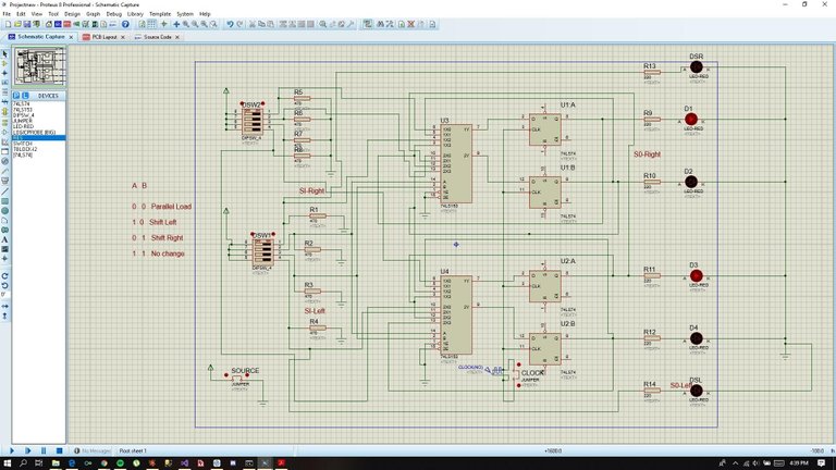
Universal Shift Registers are data that has an output with regards to the parallel in and parallel out function. Here's a sample of my inputs A = DSW2 (Top switch), B = DSW1 (Bottom switch), If A has 0 input and B has 0 input it's output is Parallel Load where all LED are on. If A has 1 input and B has 0 input it's output is Shift left where LEDs are emitting to the left side, If A has 0 input and B has 1 input it's output is Shift left where LEDs are emitting to the right side, and lastly if A and B are both 1 the output of the register is no change, it means the last register that function will be thesame on the current output.
Design Making using Protues
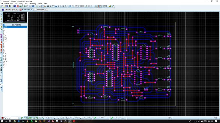
This is the actual PCB Layout of the Universal Shift Register. It's quite hard to manually design so I used automatic route to make it easy for me to manually arrange the bottom copper (Blue lines that connects all the components) also the red lines are the jumper wire it is found on the top of the board where components are found. I used jumper because some of the bottom copper are not connected and it's hard to re route again. The violet circles are the holes in the pcb wherein where you put the components.
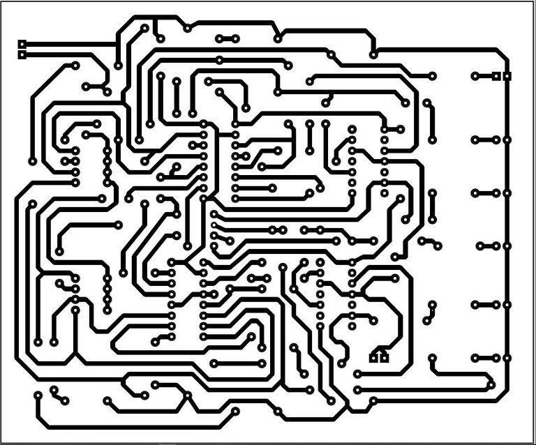
This is the .PDF file of the board that I make. I used inkjet printer(laser print) and glossy photo paper to print the output file of protues the .PDSRPG file.
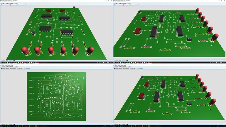
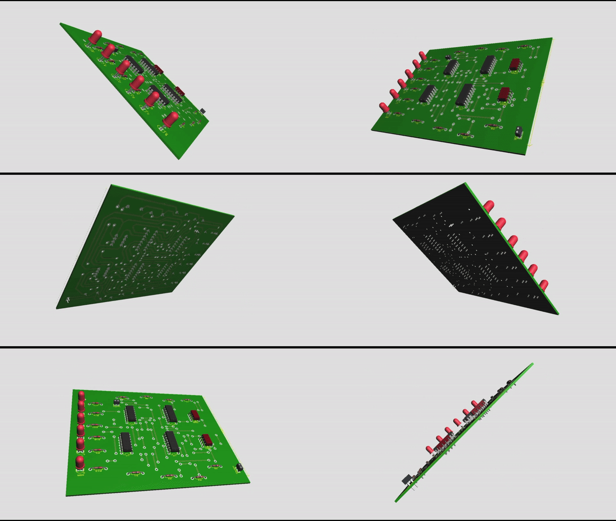
Here's a sample GIF that I make. I used windows built in video recorder to record the 3D video on proteus and after I record the video I edited it on Online GIF maker to make it an GIF file.
Materials used
- 74LS153 (Mutiplexer)
- 74LS74 (D - Type flip - flop)
- Switch
- Solid Wires
- 6 Red LED
- 220 Ohms Resistor
- 4 x 5 inch Circuit Board (Transparent)
- Ferric Chloride
Thanks for using eSteem!
Your post has been voted as a part of eSteem encouragement program. Keep up the good work! Install Android, iOS Mobile app or Windows, Mac, Linux Surfer app, if you haven't already!
Learn more: https://esteem.app
Join our discord: https://discord.gg/8eHupPq