Hello, hivers!
This post is part 2 about building another guitar amplifier. To build this amp, I modified an existing PA amp for use with guitar. In the previous post, I explained how I started the process. In this post, I'll explain how I decided to change the power tubes to a different type, and the work that was involved in that process.
The friend that I built this amp for had requested that I build the amp to use EL-34 power tubes instead of the original 7868 tubes or the 7591 tubes that I was replacing the 7868s with. After checking the specifications on the EL-34s and comparing them to the 7591s, I determined that because of the heater current required by the EL-34s, I would only be able to use a pair of them instead of the 4 original tubes. Because the heater current required by the EL-34 is twice the current required by the 7591, I wasn't sure the heater winding in the power transformer could handle the extra current required by 4 of the EL-34s, it wasn't designed for that much current.
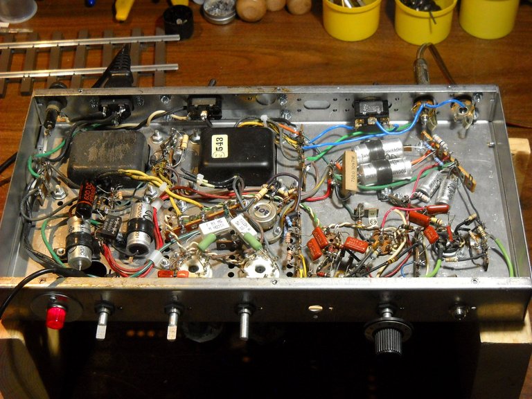
I had previously installed 4 power tube sockets, so I removed 2 of them because I didn't need them. I then used the space for the parts necessary to set up the remaining 2 sockets for the EL-34s. After I had that wired up, I also decided to put the power switch on the back of the chassis, and use that hole for the power indicator light.
This is what that configuration looks like.
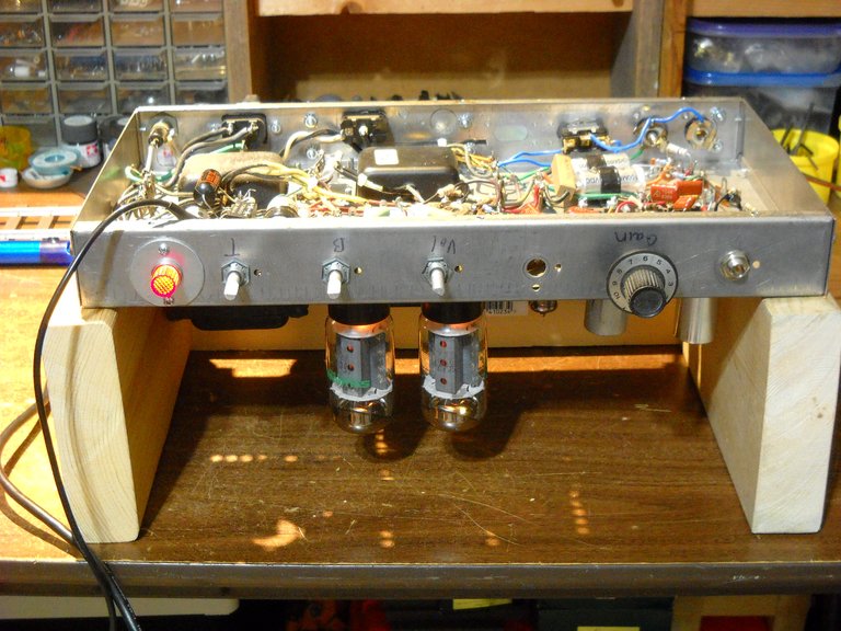
This photo is with the tubes in the amp.
One thing I had not planned on was how tall the EL-34 tube is, and if it would fit inside the amp's case. I discovered that I could not get the chassis into the case with the power tubes in their sockets. Because of that, I decided to change the power tube sockets again, from top mounted sockets to bottom mounted sockets. That extra 1/4 inch of space allowed me to get the chassis into the case, just barely. Though the tubes did fit into the case, there would be no way to change them other than taking the chassis out of the case. There wasn't enough space to pull them out of their sockets while the chassis was in the case.
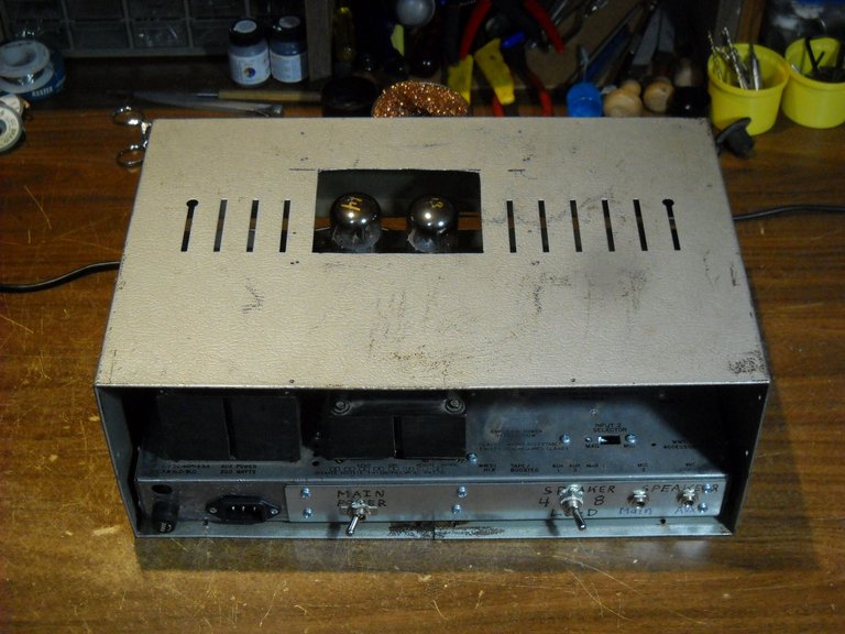
To solve that problem, and also the heat problem from the tubes being so close to the top of the case, I decided to cut a hole in the top of the metal case above the tubes. That would allow space to be able to remove the tubes, and also provide ventilation.
Here's what that looked like.
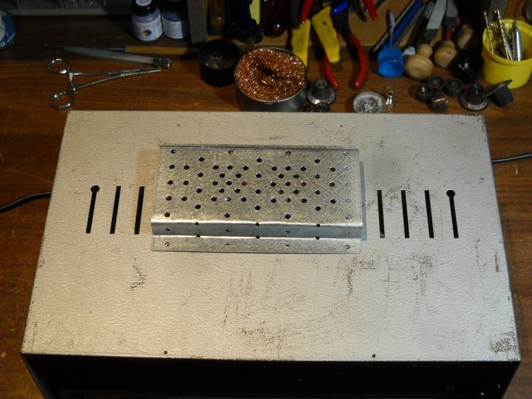
Next, I needed to make a ventilated cover for the hole. I didn't want to just have the hole in the top. To make the hole cover, I used a galvanized "splice plate" that's used for roof truss construction to make the cover. The splice plate is full of nice tidy rows of holes that would normally be used for nailing the plate onto a joint in a roof truss, so it was pre ventilated. I had to do a bit of bending to get thew shape I wanted, but I did that with a bench vice.
Here is how it turned out.
After I was satisfied with the fit of the hole cover, I took the chassis back out of the case and repainted it to make it look better. I think the amp project came out pretty well.
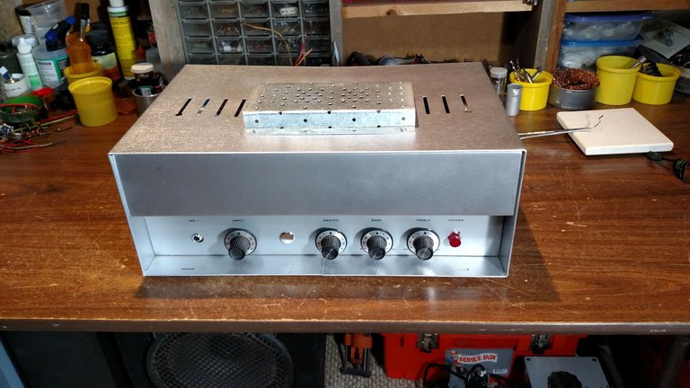
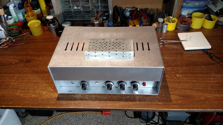
That's the end of this 2 part series about this amplifier build. I hope you found it interesting.
Thanks for checking out the post!

