Intro
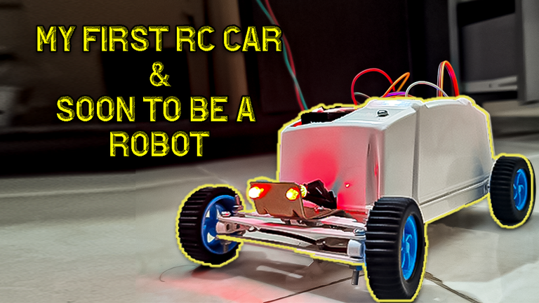
Hello and congratulations again to all of you dear friends in the DIY Hub community, I hope you have started your day well. Well, today I am back with another cool new update on my remote control robot as you can see in the photo below, so stay tuned for the rest of this text.
And a video of the whole process on my youtube channel:
Please like, share and subscribe!
1. Fixing the Gears Problem
So as I mentioned before, I took the gears to use on my RC Robot out of a DVD player and they weren't a perfect fit, but I had to go with whatever I had:
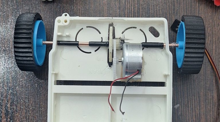
As you can see on the picture, both gears are big, the problem is big gear on the motor side means more starting power and torque is to be driven out of the motor and this motor doesn't have that much power, So I decided to get a new smaller gear and replace it with that one:
![20250202_205644.mp4_snapshot_01.43_[2025.02.04_06.25.02].jpg](https://images.hive.blog/768x0/https://files.peakd.com/file/peakd-hive/hadif66/EoErXntB7naNsLuppUyTeoYDqVNZPxFNmNdGiiYG8te7p6pQyF1t18JJwQX5EZNZ8jg.jpg)
Fixing that problem caused another, So now the gear can't be fitted at it's place without the DC motor touching the rear shaft:
![20250202_205644.mp4_snapshot_02.00_[2025.02.04_06.27.06].jpg](https://images.hive.blog/768x0/https://files.peakd.com/file/peakd-hive/hadif66/23u65BxHnpgveQkaKsghydsEebzyLkQ9wzVhPKrceTtLYoLQwN9ogP97BqG8YzjYUxT1L.jpg)
To solve this problem I took out the part of plastic that was holding the motor inside the DVD player :
![20250116_235301.mp4_snapshot_00222.54_[2025.01.17_02.35.05].jpg](https://images.hive.blog/768x0/https://files.peakd.com/file/peakd-hive/hadif66/23wqgbBzqfpQnAzjM9PTy7uTycSgHszr45Q4GztRhVLYRfpSUTv1VAuzQcVcnK1RcEgxz.jpg)
And started to shaping it to the right shape using a mini drill:
![20250202_225625.mp4_snapshot_01.43_[2025.02.04_0sss6.44.29].jpg](https://images.hive.blog/768x0/https://files.peakd.com/file/peakd-hive/hadif66/23wgKcjSvjZFZpHaTRdg3XrGDThfk4Fy8PfS3HEP6QGFp33bgQKXCJ2QuLUitRJ6EanVu.jpg)
Then I glued the Motor to the holder using Hot-melt adhesive :
![20250202_230305.mp4_snapshot_00.23_[2025.02.04_06.48.34].jpg](https://images.hive.blog/768x0/https://files.peakd.com/file/peakd-hive/hadif66/EoeFQshpx7JkDWoP4bDUhgne3tAUyx5nhD587Bo8dW65VXCc1ERmwWgG7eXkHbKYghZ.jpg)
And next I glued those to the chassis:
![20250202_230305.mp4_snapshot_00.58_[2025.02.04_06.48.49].jpg](https://images.hive.blog/768x0/https://files.peakd.com/file/peakd-hive/hadif66/23vsShPhpLxTUm8cNYhgAeqHbHUuTBp31sjNSvc8a9MMSWpXDDm5mTqvhTk9d6mbmmbTm.jpg)
![20250202_230305.mp4_snapshot_01.08_[2025.02.04_06.49.04].jpg](https://images.hive.blog/768x0/https://files.peakd.com/file/peakd-hive/hadif66/23uQvjwjWJ8nnwyFPiUBfzYqV2HXc9DkyTS5Ub5ytWKDhuPAByS2FnoNN658mwNLhyCFV.jpg)
And that way we fixed the problem with high torque and force needed at start, there is better way to do this by adding another gear but for now this is going to make things work:
![20250202_230305.mp4_snapshot_01.24_[2025.02.04_06.57.11].jpg](https://images.hive.blog/768x0/https://files.peakd.com/file/peakd-hive/hadif66/23vi21KsHiKwkYQAgBcJYmPeyAkLgnJ5LEmNeyMkadULBmZASNWZrKvaMDCja8wCxTw7H.jpg)
2. Adding Headlights
So next thing that came to my mind, I thought adding a headlight to the robot not only makes it looking cool but also it may be useful when I add a camera in the future, So in dark places we can turn the lights on.
So having that in mind I started by looking for LED's in my stuff, until I found a bunch of 5mm LEDs:
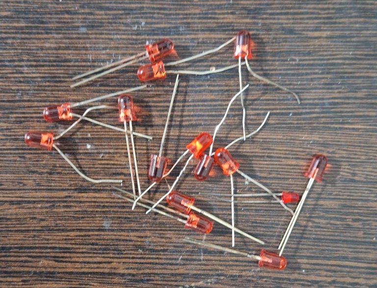
But in order to make the LEDs work safely without burning them you need to add resistors between the positive leg of the LED and GPIO pin of the ESP32, for these LEDs that I have, a 220 ohm resistor is a good fit to have good enough brightness and safely using it:
![20250203_073142.mp4_snapshot_00.27_[2025.02.04_07.18.13].jpg](https://images.hive.blog/768x0/https://files.peakd.com/file/peakd-hive/hadif66/23xedbKhD63XXYW2e61cQL1RbWRkt9JJQpGSg95W15mgbGcAdgNuduJA65u9pPq9d6zwW.jpg)
So I soldered the ground legs of the LEDs together to a wire which later goes to the ESP32 ground pin:
![20250203_071648.mp4_snapshot_00.29_[2025.02.04_07.20.03].jpg](https://images.hive.blog/768x0/https://files.peakd.com/file/peakd-hive/hadif66/23wgKmrVEqwjkF4JfcHGYJ2t6Af2Lc7e6JDERNESCahw6hjpe66KW5w4QWbmzYSE8vtMP.jpg)
And soldered a 220 Ohm resistor to each positive leg of LEDs, and a wire to each pin which then will go to the related GPIO pin on the ESP32 (GPIOs : 18,5):
![20250203_071648.mp4_snapshot_03.49_[2025.02.04_07.21.57].jpg](https://images.hive.blog/768x0/https://files.peakd.com/file/peakd-hive/hadif66/48SMFhMkd848aF26LzxiSx1Utc9w9Cz4GsvCPuKaP2oSiVBXhhWur9sUPJpYiqzwbZ.jpg)
![20250203_071648.mp4_snapshot_07.48_[2025.02.04_07.22.51].jpg](https://images.hive.blog/768x0/https://files.peakd.com/file/peakd-hive/hadif66/23wC9nhLFzZBKeqHcABwEK4s7S3J6wPXUdqZo62nLPhCt3r6qG2yVexLST9khEytq1r5A.jpg)
Now that the soldering is done I need to cover the naked wires so they won't collide and cause problems so I used electrical tape to do it (Better option is to use varnish):
![20250203_072821.mp4_snapshot_01.44_[2025.02.04_07.34.26].jpg](https://images.hive.blog/768x0/https://files.peakd.com/file/peakd-hive/hadif66/23xKxZUu7yAvkx5Hi5u65ZLFrKypg3Ff4D9FYBfUsuz3krmnD8RuBADDvCMyUxLaVnYFr.jpg)
![20250203_073142.mp4_snapshot_00.36_[2025.02.04_07.35.29].jpg](https://images.hive.blog/768x0/https://files.peakd.com/file/peakd-hive/hadif66/EogNpiDtpWzWT7SN6GPDe5Pesd5PDaW5H5ofztde1Nvnj3EbUBr1mzyQGGfg6fK97xw.jpg)
Now that the LEDS are ready we need to put a holder on the front of the Robot to keep everything together so I had a bunch of these metal parts which are used in curtains, I used another one and screwed it in the front:
![20250203_034924.mp4_snapshot_00.35_[2025.02.04_07.38.47].jpg](https://images.hive.blog/768x0/https://files.peakd.com/file/peakd-hive/hadif66/EoAZETwsoXAMyMi3cT22gvF7i3neJ8T47yK11FXPmTQxL47mQb1o3aTPfwn8s8c9BrG.jpg)
![20250203_034924.mp4_snapshot_05.36_[2025.02.04_07.39.05].jpg](https://images.hive.blog/768x0/https://files.peakd.com/file/peakd-hive/hadif66/EoGxvmTGdPuGJA8wiY89QiRKFrk4WJXL8VCwXfkeTpZUyMg6xDJt7CsRg4mSSrviGrN.jpg)
![20250203_073425.mp4_snapshot_00.01_[2025.02.04_07.39.52].jpg](https://images.hive.blog/768x0/https://files.peakd.com/file/peakd-hive/hadif66/EpLgYa8R1mdZdEvPyube5BUC3stePVEdSzb8nddXwxPACrPPvGGUAEjxxfVMRLLAsy2.jpg)
3. fitting everything in the box
The next and maybe the last problem was that the box that I used as the body of the robot doesn't have enough room for keeping everything inside:
![20250131_062616.mp4_snapshot_00.00_[2025.02.04_07.46.04].jpg](https://images.hive.blog/768x0/https://files.peakd.com/file/peakd-hive/hadif66/23tvijBsm6qQ6S5UEKDoz6cCQeguPx21Zqw8zz1DiR43kmurp3DNRLXFPFBbJ8d4ErRcH.jpg)
Even though I didn't like to change the cool shape of the box, I had no choice but to cut some pieces at the top, so I marked it to cut:
![20250202_235205.mp4_snapshot_00.21_[2025.02.04_07.49.15].jpg](https://images.hive.blog/768x0/https://files.peakd.com/file/peakd-hive/hadif66/23uFVziPunY6js69dvTfLeDBbcEccMQm6xr7KAZtB8HqdpanczM1AmwFApiYfk6yfVK69.jpg)
And cut it using the mini drill:
![20250202_235205.mp4_snapshot_00.46_[2025.02.04_07.49.25].jpg](https://images.hive.blog/768x0/https://files.peakd.com/file/peakd-hive/hadif66/23vsQDDvjScBh9uvRSsj7Up8o2PZYjDxUdQckuPjeVyM7xTSdSvhqAMFMjRThJ7J7mXmg.jpg)
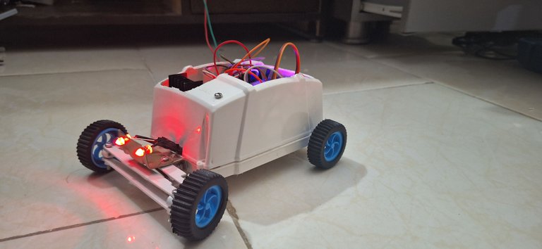
And finally the whole thing came together as planed:
![20250203_015642.mp4_snapshot_00.00_[2025.02.04_07.52.23].jpg](https://images.hive.blog/768x0/https://files.peakd.com/file/peakd-hive/hadif66/23xKxeHwYFSAj23VfW1XSbpDWYrVdeLKKeBThdwJk5eXJEqpngrKYU1t2MmE9uPTxsHE7.jpg)
Outro
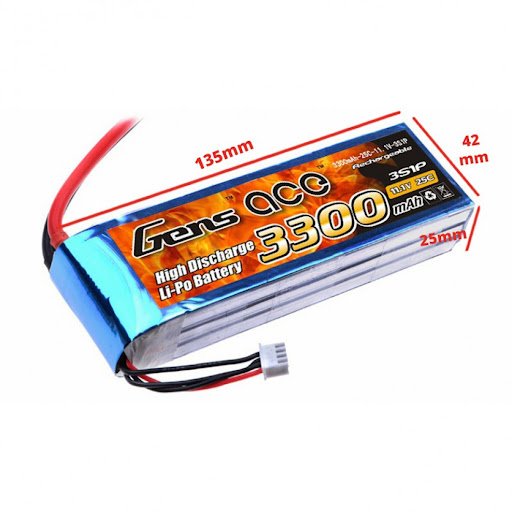
Thank you for following this text and content so far, and I must say that I want to add more updates to this robot, which requires a series of sensors and cameras, etc., which I will try to get over time, and another very important piece is an 11.1 volt LiPo battery:
Which are expensive batteries, but I am trying to find cheaper ones. I must also say that I have a number of other content in mind, such as continuing the ESP32 tutorials that I started in 3Speak:
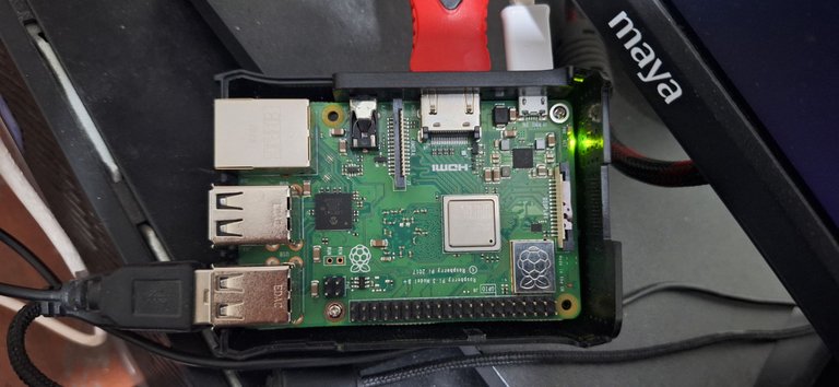
and in addition, I am working on cool projects using the Raspberry Pi, which you will see in the future. I've found an old raspberry pi 3 which was laying in the corner useless, So I brought it back to life to make more cool projects.
Happy Building! and have a good day.
Wow! You embarked on such a mind-blowing project and we are glad that everything is going smoothly. We admire your creativity and we wish you all the best in your future endeavors. Well done and thanks for sharing.
Thank you, I appreciate your kind words and support. It means a lot to know that my work is inspiring others. I'll be back withmore exciting projects. Stay tuned for more 👍🙏
!PIMP
!LUV
(2/5) sent you LUV. | tools | discord | community | HiveWiki | <>< daily@hadif66, @happyphoenix
View or trade
BEER.BEERHey @hadif66, here is a little bit of from @happyphoenix for you. Enjoy it!Learn how to earn FREE BEER each day by staking your
BEER.!BEER