Hello DIYHUB community!
As many of you have seen in my previous posts, I have been working on a remote-controlled robot powered by an ESP32 microcontroller, a small DC motor, and a servo motor.
Today, I’m thrilled to share some exciting progress – my robot is finally moving! However, there’s also some bad news: the two lithium batteries I salvaged from an old laptop didn’t last long. So, for this demo, I had to use a direct power source with an adapter. But don’t worry—I’m not giving up and will keep pushing forward.
1. Improvements and Modifications
1.2 Front Steering System
I started by reinforcing the front steering mechanism. Initially, I used metal brackets attached with hot glue, but after testing, I realized this setup wasn’t delivering the desired results.
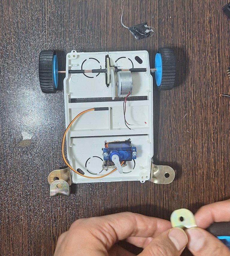
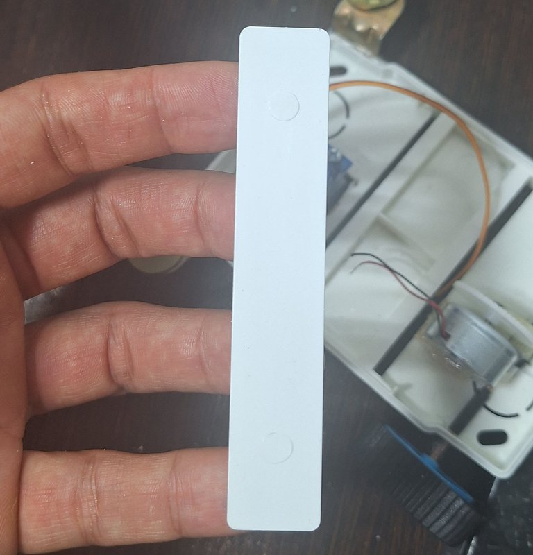
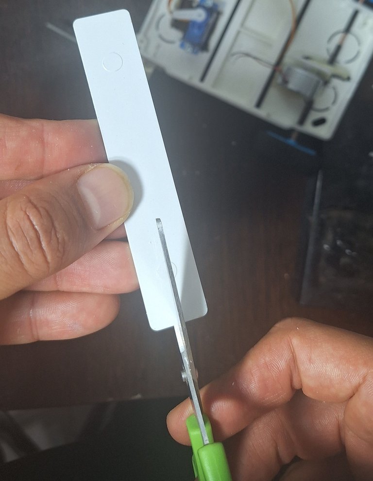
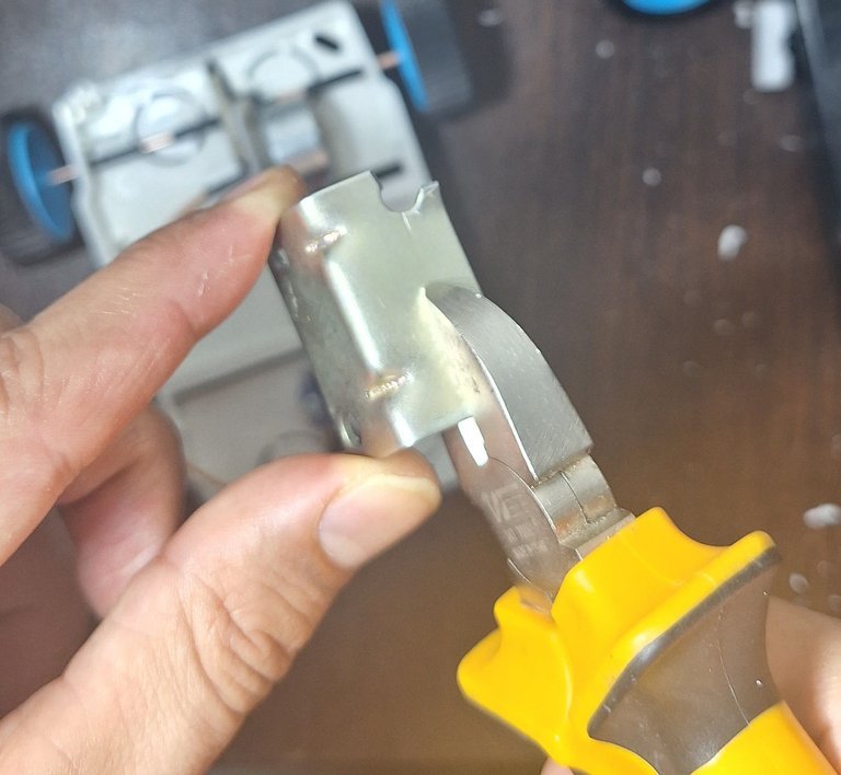
After searching through my workshop, I found some plastic brackets and envisioned a more efficient way to use them.
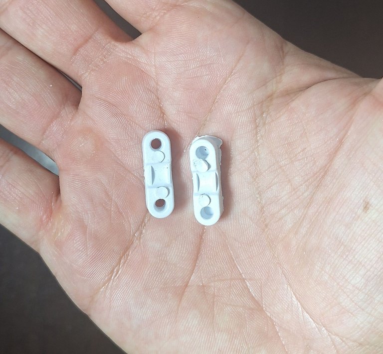
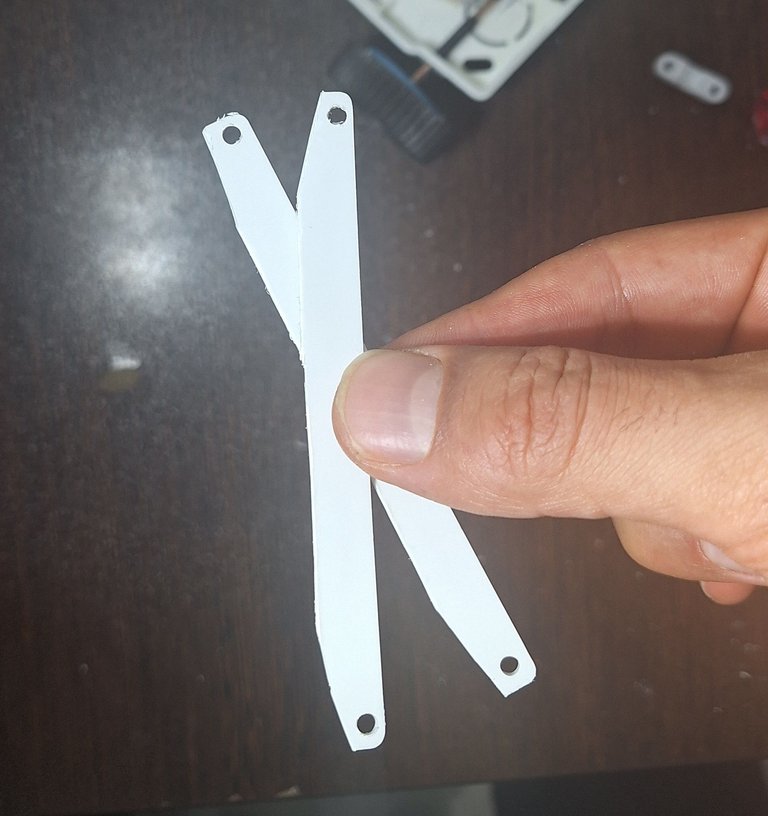
I drilled a few holes, reshaped them, and eventually created a sturdier mechanism.
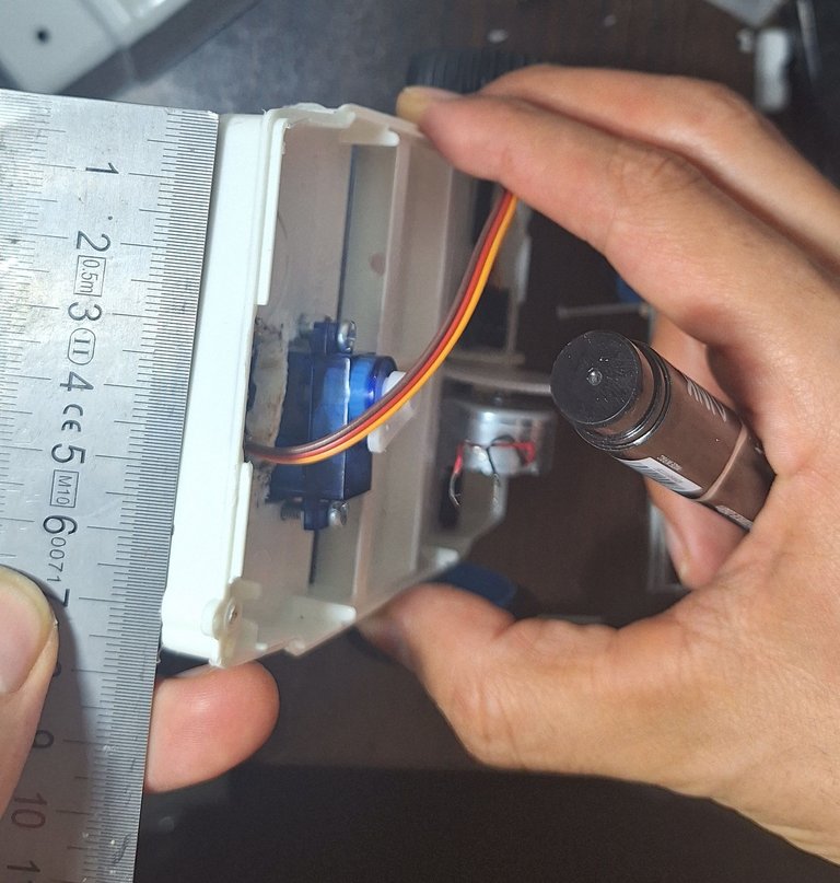
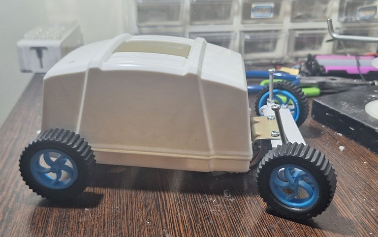
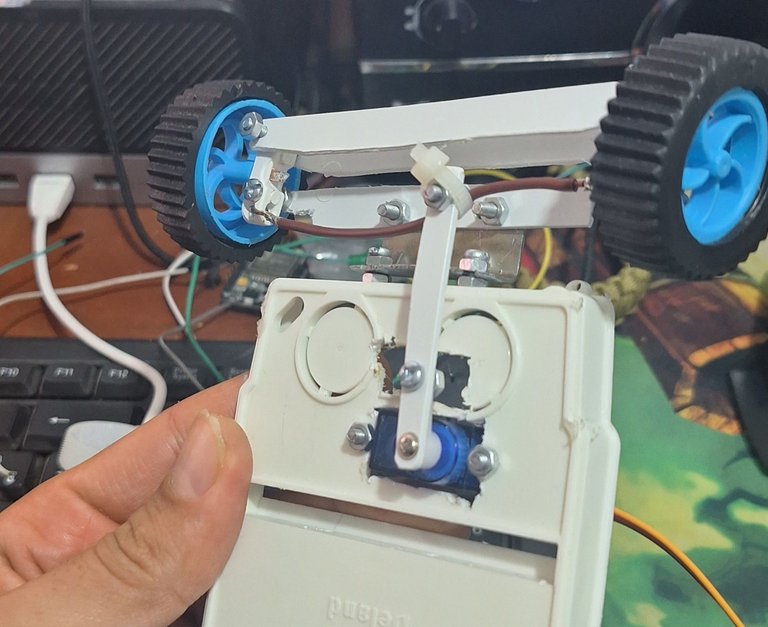
Additionally, I repurposed an unused electrical junction box as the robot’s main body. Inside, I found two plastic pieces that suited my needs. With a bit of cutting and drilling, I shaped them into functional components.
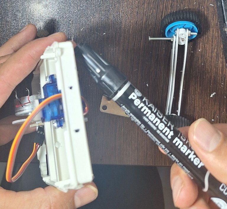
Next, I used a special curtain bracket, cut and modified it, and measured precise hole placements with a ruler and marker. I then drilled two holes on the front body to mount a metal piece securely.
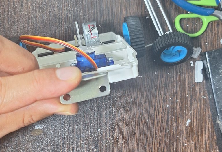
After putting everything together, I noticed that the front of the robot now had a rugged, utilitarian look—almost like an old-school Jeep or a classic Land Rover! This gave me an idea for future aesthetic modifications.
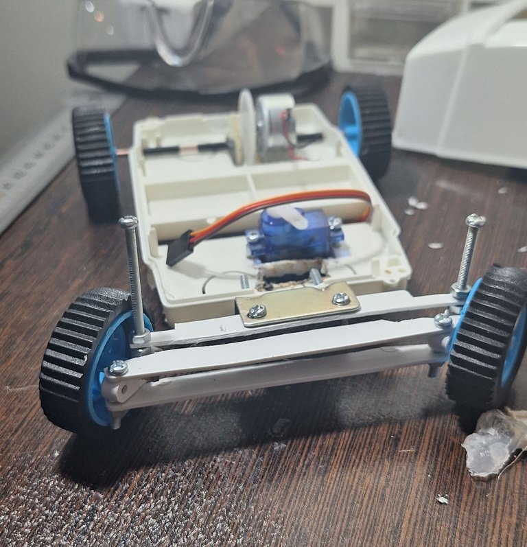
Looks pretty cool to me 😁
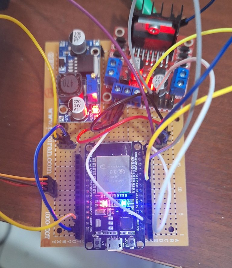
1.2 Completing the Circuit Board
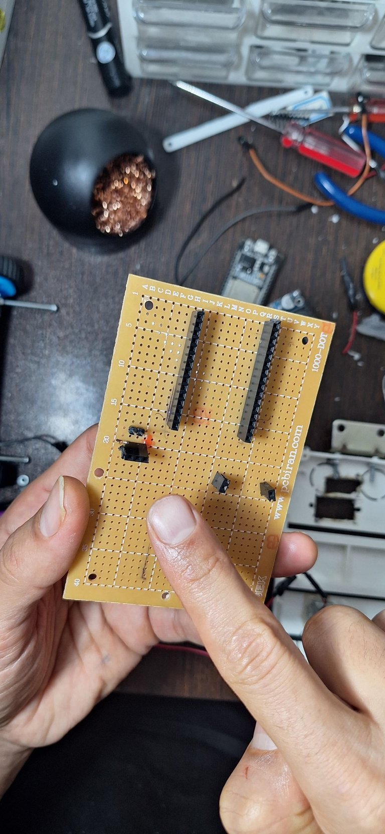
Once I was satisfied with the initial design, I focused on assembling the circuit board. Since I was using a perfboard, I first planned the layout mentally, ensuring an efficient wiring scheme before starting the soldering process. Here’s how I wired it:
DC motor direction pins: GPIO 22, 23
DC motor enable pin: GPIO 19
Servo motor pin: GPIO 25
Power connections: Properly routed VIN and GND
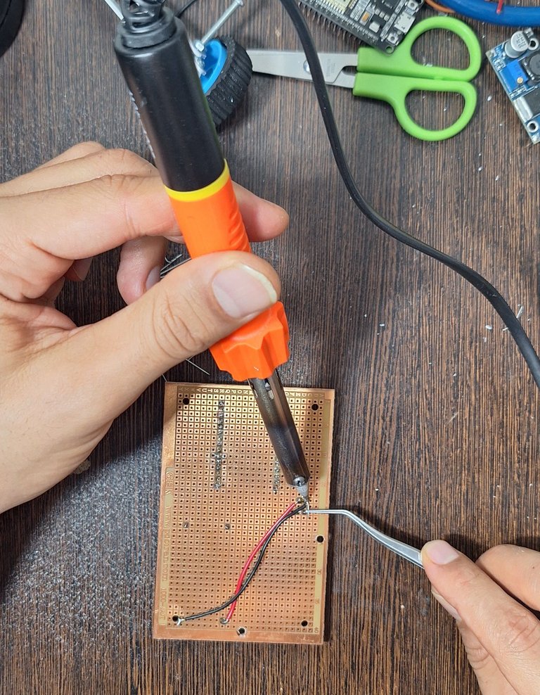
For power management, I needed 5V for the ESP32 and servo motor and 12V for the DC motor. To achieve this, I wired the system so that the power supply could deliver both 12V directly and 5V through a step-down converter. I used two different methods for the connections: direct soldering and soldering with insulated wires to ensure durability and reliability.
11.2v for the DC motor:
![20250130_204054.mp4_snapshot_00.16_[2025.01.31_07.20.04].jpg](https://images.hive.blog/768x0/https://files.peakd.com/file/peakd-hive/hadif66/23vi5t1SvLC4npjw2VrRQN9MsQzkanwDYDBQVhBiJNzo2T5y8JcY3jt7m2hMttkc1ny6C.jpg)
5v for the ESP32 and servo:
![20250130_204054.mp4_snapshot_00.28_[2025.01.31_07.20.27].jpg](https://images.hive.blog/768x0/https://files.peakd.com/file/peakd-hive/hadif66/23wMcNhmjGSXMwgarPdeGVysgcHgEnBdSEFNW2qoiDRQAHwSGaLBSATTFj3cZqfDzsh1z.jpg)
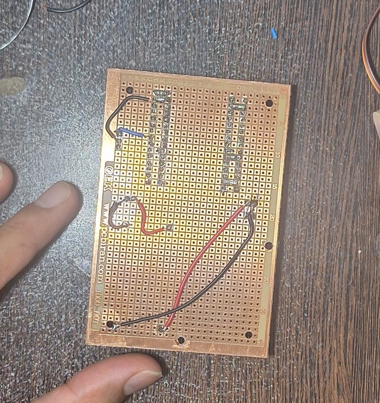
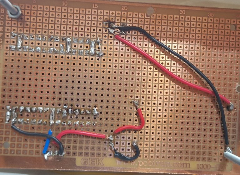
The whole wiring under the per board, both wiring techniques used(direct soldering and soldering with insulated wires):
1.3 Fine-Tuning and Testing
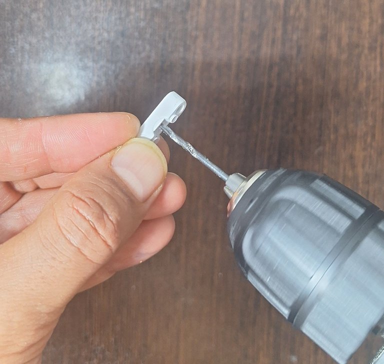
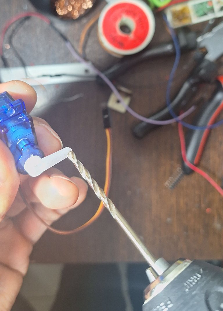
With the circuit complete, I returned to refining the front steering system. I mounted the servo motor in its designated position but realized that the attachment hole on its horn was slightly too small. To fix this, I used a drill to widen the hole, ensuring an easy fit for the screw.
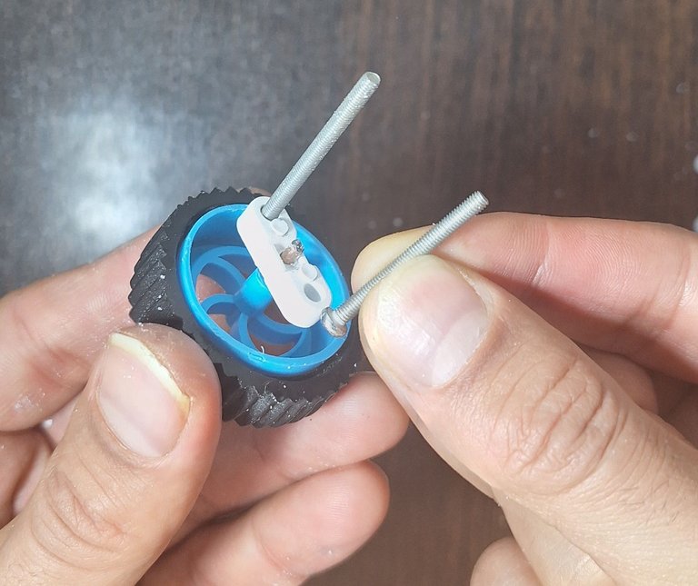
I then attached a rectangular plastic piece to the servo and connected a coated wire between the two front wheels, making sure it was taut and secure. The final step was to fasten the servo arm to the center of this wire using a zip tie. This setup allowed the servo to precisely control the front wheels’ movement.
During the initial tests, I set the servo’s movement range from 0° to 180°, but this didn’t match the desired steering angles. After trial and error, I found that the optimal range was 95° to 115°, with a default center position at 107°.
I ran multiple tests to ensure that the steering was responsive and stable. Watching the robot move and turn accurately was incredibly satisfying—one of those moments when all the effort finally pays off! Here is a video of the results on my YouTube channel:
2. Battery Failure & Lessons Learned
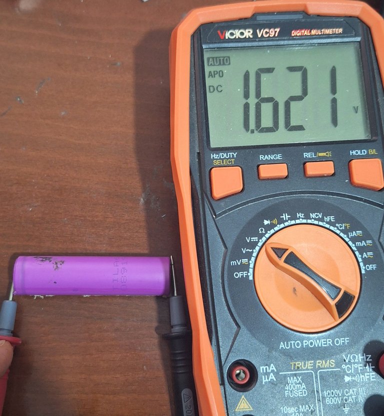
When everything was ready, I attempted to power the system using my salvaged lithium batteries, but they had completely failed. This led me to investigate how to determine whether a battery is truly dead.
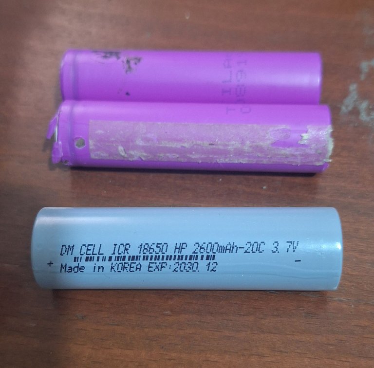
How to Check if a Lithium Battery is Dead
To diagnose a dead lithium-ion battery, simply measure its voltage with a multimeter. A healthy 3.7V lithium-ion battery should never drop below 3V when empty. If it does, it may no longer be safe or functional.
In my case, the batteries were well below the usable voltage range, confirming that they were completely dead. This was disappointing, as I had hoped to power the robot wirelessly.
For now, I had to rely on an adapter to run the demo. However, this experience taught me the importance of using reliable power sources for robotics projects.
What’s Next?
I’m far from finished! Here are my plans for the next set of upgrades:
- Upgrade to stronger materials like aluminum for key structural parts.
- Find better batteries to replace the failed ones. Li-Po batteries would be ideal, but they are expensive, so I may settle for lithium-ion.
- Paint the robot body and add a custom design—any suggestions?
- Further optimize performance, refine the movement algorithm, and possibly add a wireless control interface.
- Explore sensor integration to add automation capabilities.
This project is a continuous learning experience, and I truly appreciate all the support and feedback from the DIYHUB community. Let me know what you think—do you have any suggestions for improvements? Any ideas for modifications or enhancements?
Thanks for following along! I still have a lot of upgrades planned for this robot, and I’ll keep you all updated. Stay tuned for the next improvements!
🚀 Happy building!
!LUV
This is a real talentI feel like calling you a magician @hadif66
Wow, you just keep improving every project you undertake, it really is exciting to visit your blog and see your progress. Thank you so much for sharing it in our DIYHub community...
Wow! This is incredible. We are happy that your robot can finally move, this is no easy feat and as a community, we celebrate your creativity. Well done and cheers to more creative ideas.
Thank you so much! I truly appreciate your support and encouragement. There are many exciting updates coming soon, and I’ll be sharing even more diverse tutorials in the near future. Stay tuned!
Congratulations @hadif66! You have completed the following achievement on the Hive blockchain And have been rewarded with New badge(s)
Your next target is to reach 2500 upvotes.
You can view your badges on your board and compare yourself to others in the Ranking
If you no longer want to receive notifications, reply to this comment with the word
STOPCheck out our last posts: