Intro
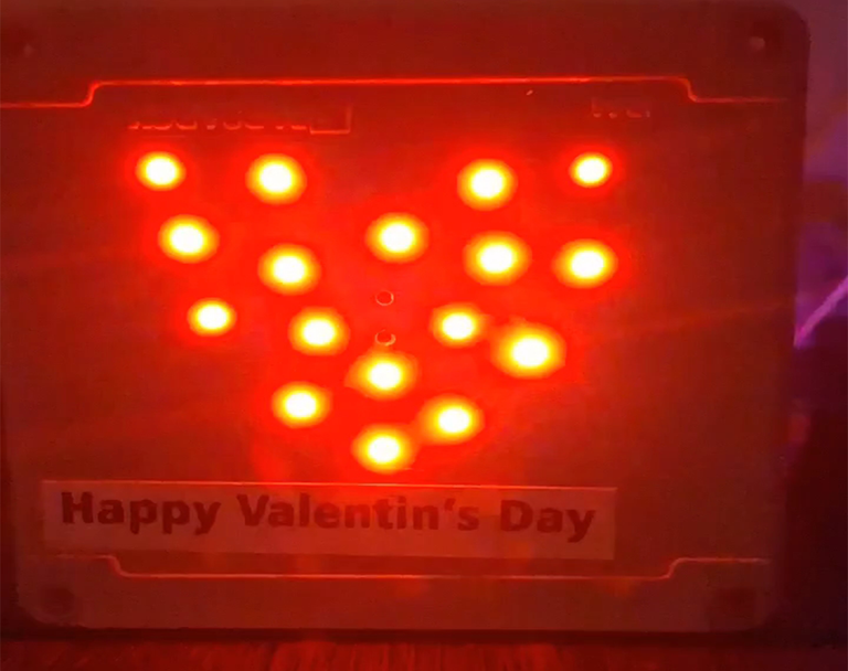
Hey everyone, I am back with another DIY tutorial, since this months theme is about the special valentine's day so I decided to once again use the power of my favorited microcontroller esp32 to create a blinking heart using some LEDs on a box. Make sure to watch the final result on the video attached down here.
Materials
- Electrical junction box
- 17 red 3mm LEDs
- 220 ohm resistors
- ESP32 microcontrollers
- Connection wires
- Breadboard
- Drill
- Glue
- paper
Steps
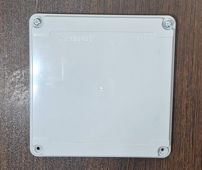
For getting started I needed a surface to put all the LEDs on it and place them in form of a heart, so after looking around for a while I've found this Electrical junction box which was unused:
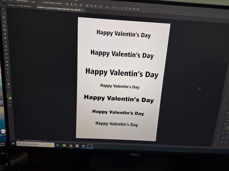
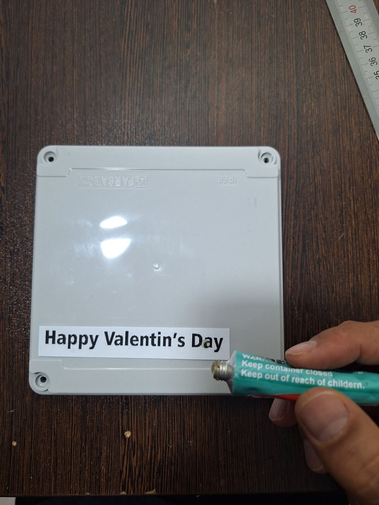
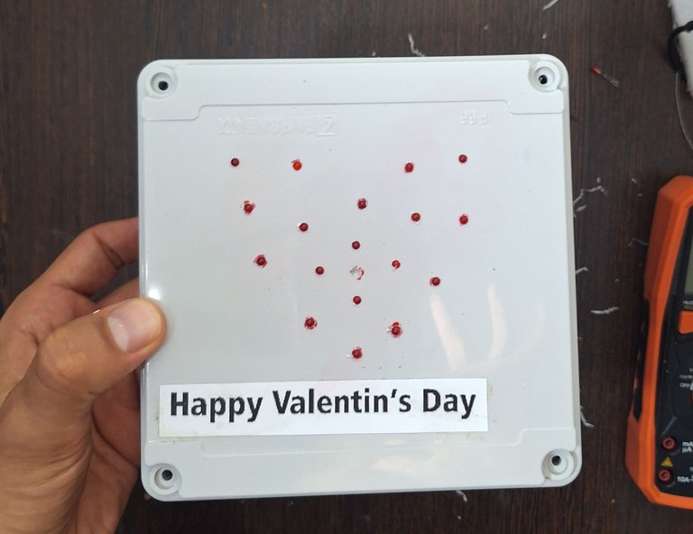
Then I printed "Happy Valentine's Day" and glued it on the box (missed an E there!):
Then I made the initial design on a piece of paper:
![20250210_125021.mp4_snapshot_00.14_[2025.02.10_22.54.34].jpg](https://images.hive.blog/768x0/https://files.peakd.com/file/peakd-hive/hadif66/23tmN1mNsQobWg3wApuXr9LWjn137VtGRFuLuif8dEqjc2n44yMeDFJTZGv2TKiCvYh6m.jpg)
Since my ESP32 only has 17 output GPIO pins, I used 17 LEDs
Next Step I draw the LED places on the box and made holes by using a drill:
![20250210_125307.mp4_snapshot_00.05_[2025.02.10_22.58.14].jpg](https://images.hive.blog/768x0/https://files.peakd.com/file/peakd-hive/hadif66/23y8v2pDDPWhGSxfvvFWWou2G6qw12SSWdYUe1RmHbQccSsWtTUKETEZbHFi38HC7ggpw.jpg)
Note: Make sure the drill's head is the size of your LEDs
Choosing the write size Drill head makes things easy so without using glue or anything the LEDs will stay in their places:
![20250210_125307.mp4_snapshot_05.37_[2025.02.10_23.02.17].jpg](https://images.hive.blog/768x0/https://files.peakd.com/file/peakd-hive/hadif66/23tvq7U8xgc8Q6bbaNXrEHCo87a4ABziCVHspyUbzry4Cu6e39d7CHnP3jr6LXEv36WzV.jpg)
So the next step is to wire everything to the microcontroller and write the code.
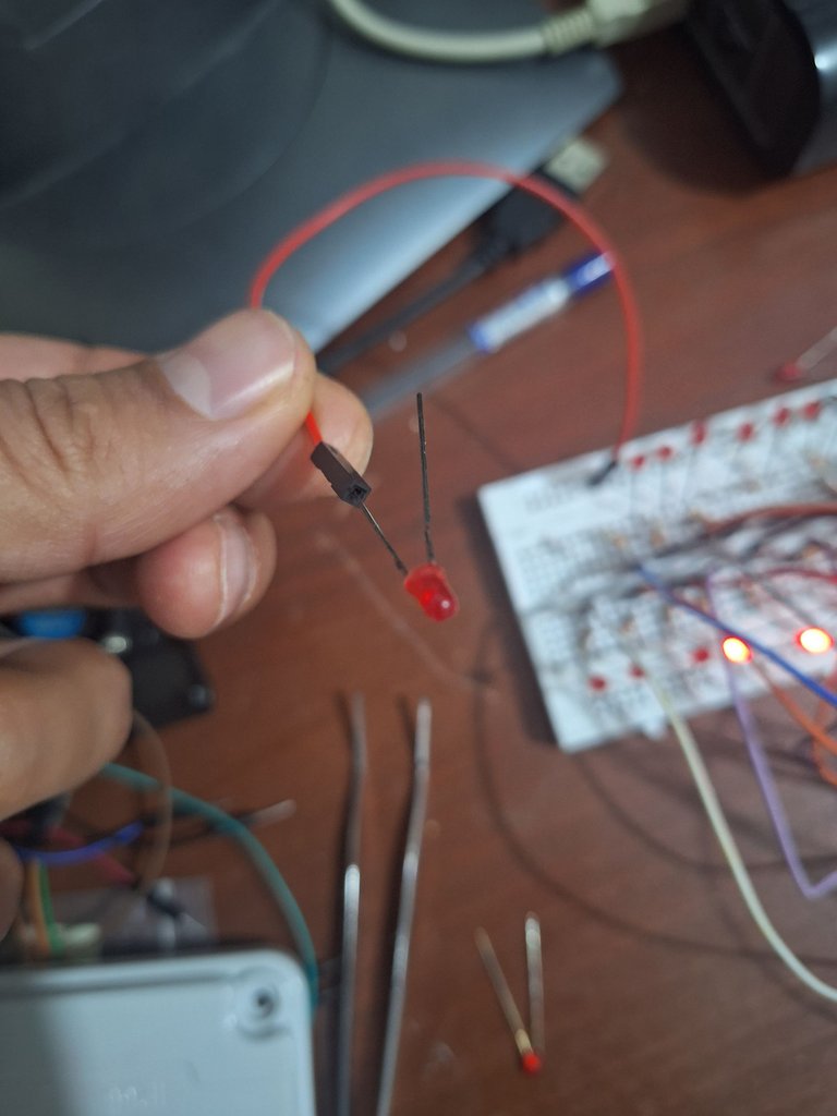
It is very important to use resistors when you want to connect LEDs to your microcontrollers, these LEDs need 2.2V to 2.4V to work and if you don't use with a resistor it may burn the LED or your microcontroller's GPIO pin so a standard resistor to use with those is a 220ohm resistor:
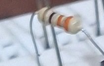
The color code is : Orange, Orange, Brown, Gold and size 1/4W
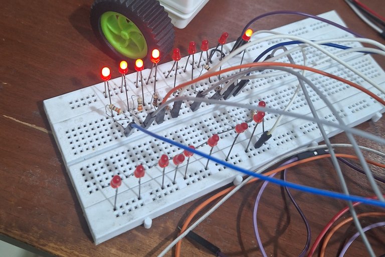
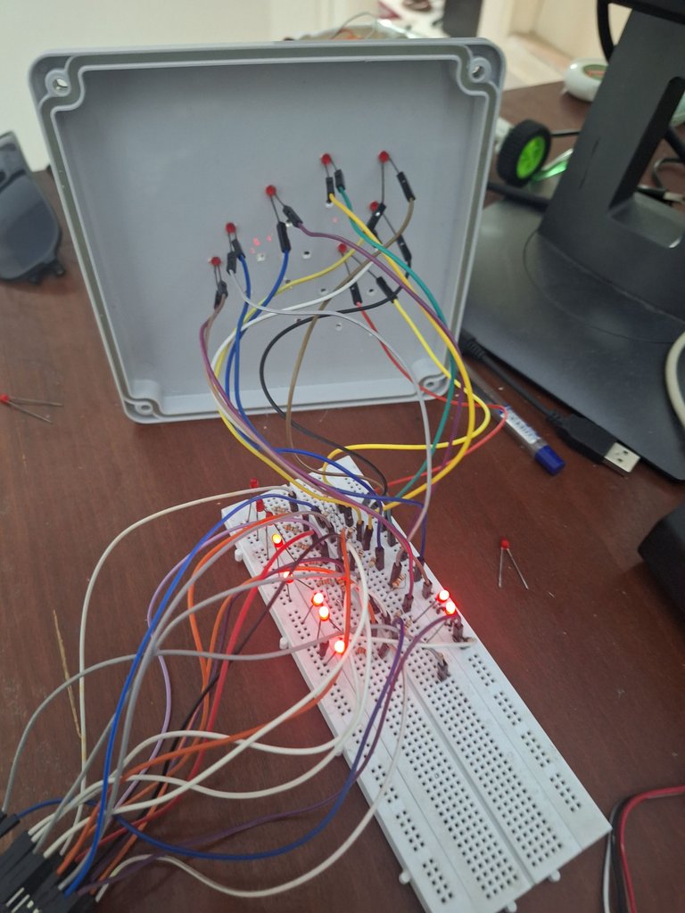
Here is how I wired everything on a breadboard:
For better understanding and clarity I draw the schematics using Fritzing:
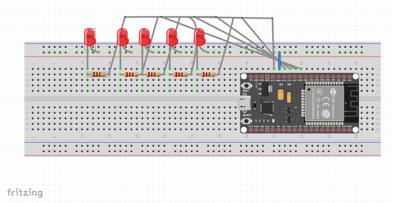
(Shorter leg of each LED goes to the ground pin of ESP32 and longer leg of each LED first connected to one side of resistor and the other side of resistor will be connected to the related GPIO on the ESP32)
My ESP32 is a WROOM Dev Kit and it only has this GPIO output pins:
2, 4, 5, 12, 13, 14, 15, 18, 19, 21, 22, 23, 25, 26,27,32,33
GPIO 34 and 35 are input only and can't be used to power LEDs
So next I used extra wires to connect to LED legs to extend their distance from breadboard to reach their places on the box:
And here is a short video on my YouTube channel of the final result:
The Arduino code:
#define LED_COUNT 17
const int ledPins[LED_COUNT] = {2, 5, 15, 4, 18, 19, 21, 22, 23, 13, 12, 14, 27, 26, 25, 33, 32};
#define DELAY_TIME 100 // Delay between LED changes (milliseconds)

void setup() {
  // Initialize each LED pin as an output
  for (int i = 0; i < LED_COUNT; i++) {
    pinMode(ledPins[i], OUTPUT);
    digitalWrite(ledPins[i], LOW); // Initially turn off all LEDs
  }
}

void loop() {
  // Turn on all LEDs
  for (int i = 0; i < LED_COUNT; i++) {
    digitalWrite(ledPins[i], HIGH);
  }
  delay(DELAY_TIME); // Wait for a specified delay

  // Turn off all LEDs
  for (int i = 0; i < LED_COUNT; i++) {
    digitalWrite(ledPins[i], LOW);
  }
  delay(DELAY_TIME); // Wait for a specified delay
}
Outro
I hope you liked this simple tutorial, if you have any suggestions or questions please write down in the comment section.
I am also made a whole tutorial video of how to code on esp32 microcontrollers by using 3 different IDEs (Arduino IDE, ESP-IDF and PlatformIO) which soon I will upload on 3Speak.
Thanks for reading, Happy crafting!
I just wonder, do you sell your works. I think its worth and useful. Nice, God bless you 😊!
!LUV
!hiqvote
(2/5) sent you LUV. | tools | discord | community | HiveWiki | <>< daily@hadif66, @happyphoenix
Thanks for the support, I believe in quality and I think for a product to be put out for sale it should have much better quality, cause you know if you value your customers or community, you will get better feedback, so for now I am working on the quality of my works and maybe in the future I make a useful product worthy for selling. Thanks 🙏.
@happyphoenix, the HiQ Smart Bot has recognized your request (1/2) and will start the voting trail.
In addition, @hadif66 gets !PIZZA from @hiq.redaktion.
Discord. And don't forget to vote HiQs fucking Witness! 😻For further questions, check out https://hiq-hive.com or join our