Sorry, people; it has been a long time since I posted an article on Hive. However, the real reason was because I was working with a friend of mine, Mr Smart of Smart Technology, on observing how he constructs his solar inverter and power station designs. 🙂
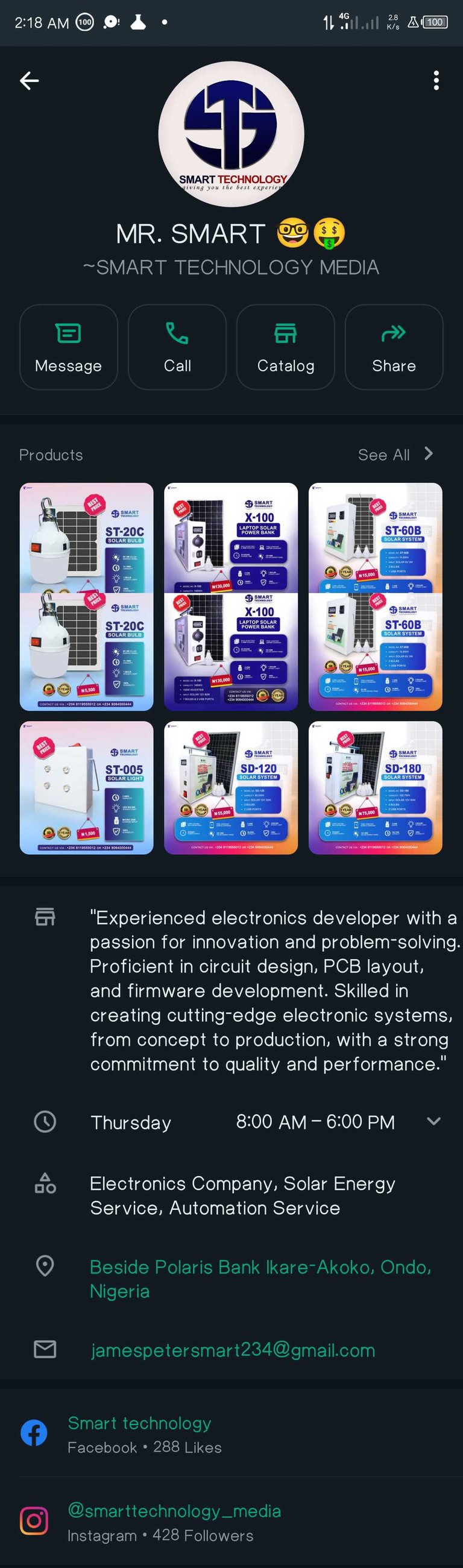
This is a screenshot of Smart Technology's WhatsApp Business handle. Here you can see some of his catalogue.
First of all, a quick background on Smart Technology. Smart Technology has been years in the making. A company registered with the Nigerian Corporate Affairs Commission, founded as recently as 2013 and fully incorporated in 2017, Smart Technology is a veritable underdog in the solar component manufacturing and installation business, based in Ikare-Akoko, Ondo State, here in Nigeria. The company specialises in electronics manufacturing, solar energy and automation, including robotics. Their designs are fully indigenous and are not mere rebranded imports from foreign manufacturers.
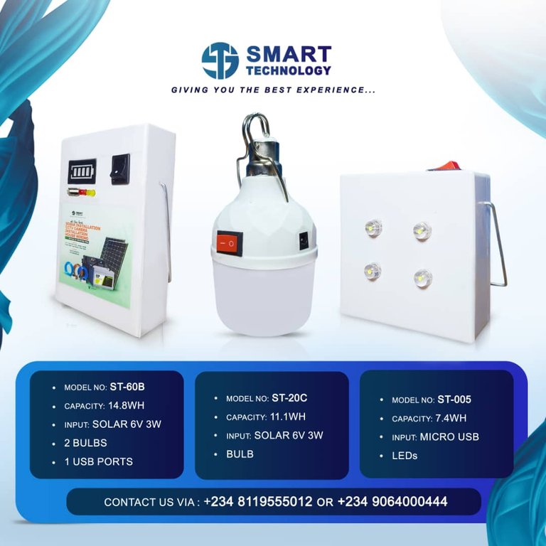
These are low-cost, high efficiency solar home illumination lighting for individuals or families on a budget.
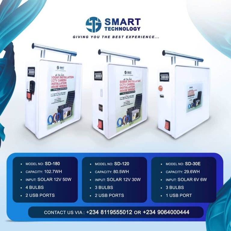
These are the entry level portable solar power station units manufactured by Smart Technology. The lightbulbs are sold along with the inverters.
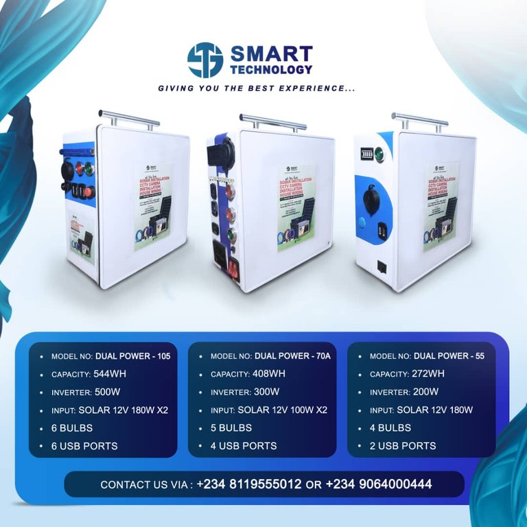
These are the higher performance, more advanced solar inverter units manufactured by Smart Technology for powering more powerful and power-consuming appliances that draw higher loads. The bulbs are sold along with the inverters.
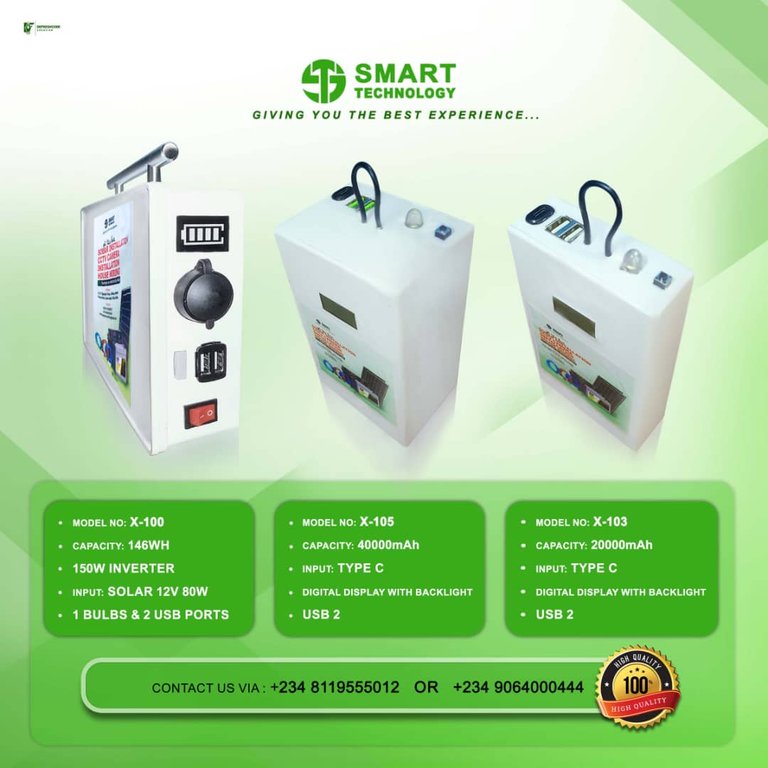
These are power bank and power station models offered by Smart Technology in different capacities.
Now I got to observe and learn how one of these models, specifically the X-100, was manufactured.
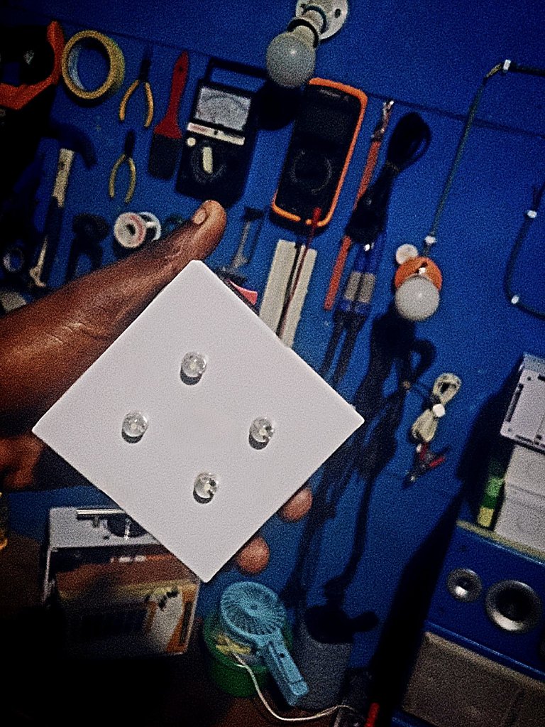
This is one of the lightbulbs, can be bought separately but is sold along with power stations like the X-100.
First of all, the electronics.are tested and the microcontroller is programmed using Arduino software or Raspberry Pi, depending on the single board computer or microcontroller used.
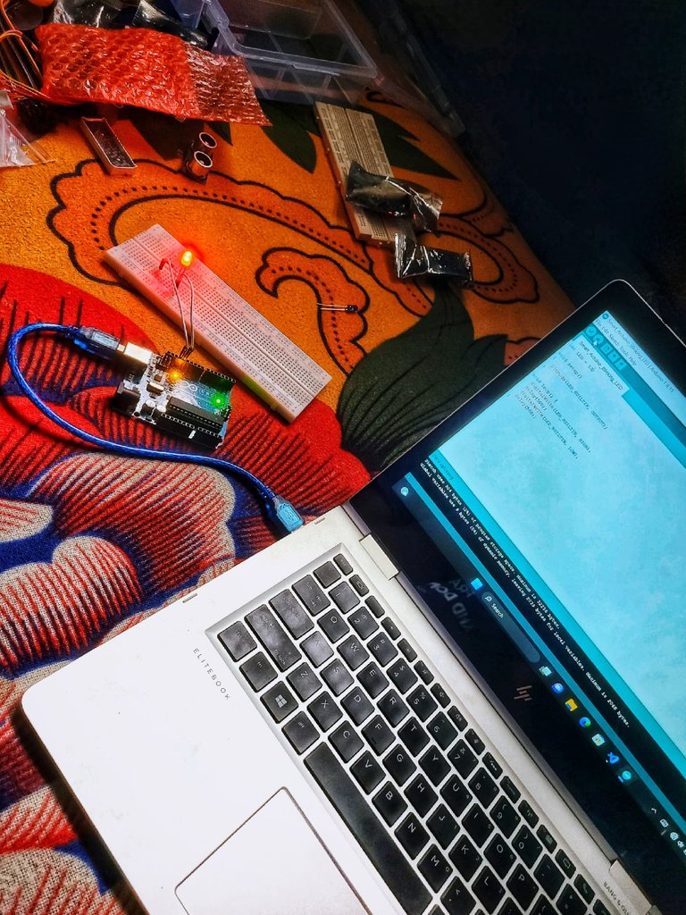
Programming an ATMega64 microcontroller for use in a portable power station design.
The obvious question you may be wondering is: How do we build this thing?
Well, it goes something like this. First of all, we need to:
- Design a power stage with MOSFETs for DC-AC conversion.
- Program the ATMega64 to generate PWM signals for inverter control.
- Implement an MPPT algorithm to optimize the solar panel efficiency.
- Add voltage and current sensing circuits for monitoring.
Then we design the battery. 🙂
For 12V 80Wh 148Wh battery system:
- Use 4 series connected 2 parallel lithium-ion battery cells (4S2P configuration).
- Implement five battery management system (BMS) controllers to balance and protect the cells.
- Connect the BMS to the ATMega64 for monitoring and control.
Additional Components:
- DC-DC converter for solar panel input with charge controller
- DC-AC inverter circuit board module to convert 12V DC battery power to stable 220V AC output at 60Hz (since this is what we use in Nigeria)
- LCD display for system status
- Voltage and current sensors (combined digital voltmeter and ammeter)
- Temperature sensors for battery and inverter to monitor temperature parameters for safe operation (NTC thermistor is most preferred)
- Cooling system to drain away the heat (heat sink and fan), because those components produce a lot of heat.
- Protection circuit (many of the components have protection built-in, but that's why we have five battery controllers and an SG3524n inverter circuit. 🙃)
To build a solar-powered inverter with the ATMega64, you’ll need a few essential parts First off, grab a 12V solar panel that turns sunlight into DC power, which gets stored in a battery. For this setup, you’ll use a 12V 80W 148Whr battery made by connecting four 3.7V Li-ion cells in series to reach 14.8V, and then linking two of those series in parallel to boost capacity. This way, you’ll have a solid 14.8V at 10Ah, adding up to 148Whr.
The battery management system (BMS) has five controllers that keep an eye on the charge levels in the cells and make sure everything stays balanced for safe and efficient use. It also protects against overcharging, over-discharging, and short circuits.
The ATMega64 microcontroller controls every major component as the central processing unit, checking the battery levels, controlling solar panel charging, and managing the inverter. The DC-AC inverter changes the 12V DC from the battery into 220V AC power for home use.
Additionally, the microcontroller can take care of things like MPPT (Maximum Power Point Tracking) to make sure the solar panels are working at their best, and it also helps with controlling the inverter, like generating sine waves.
We've also got a voltage regulator, capacitors, diodes, and a transformer in the mix. Everything is built into the SG3524n inverter IC. 🙂
Here's some pictures of the various components and internals 🙃:
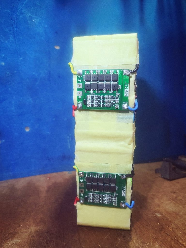
Battery protection circuits (BMS) to be installed in the solar inverter design
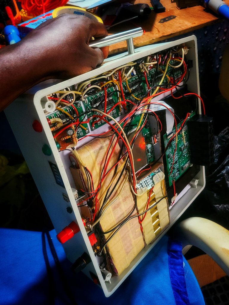
The internals of the X-100 portable power station, showcasing the five battery management system (BMS) circuits, the charge controller, the DC-AC inverter circuit, the microcontroller board and the battery setup
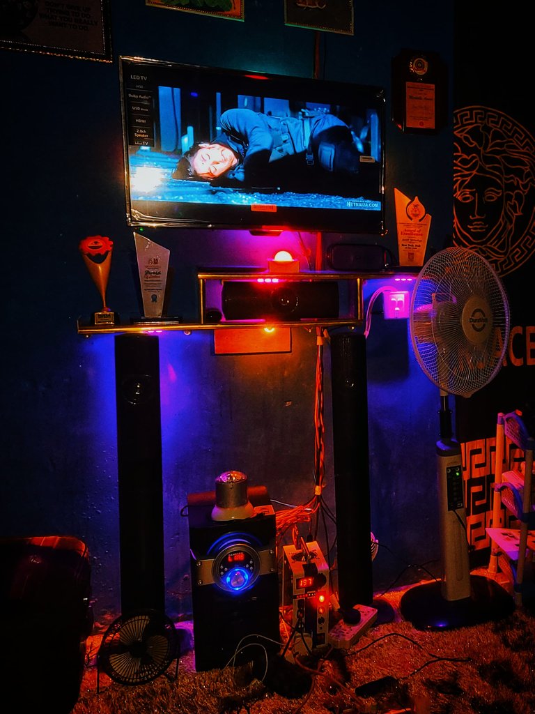
The fully-assembled inverter, now powering a television, a standing fan, a set-top box and a stereo Bluetooth MP3 music player and speaker.
The frame of the portable power stations are all made out of high-density thermoplastic for high strength, low cost and low weight, as well as being cost effective to fabricate. These materials were all locally sourced and fabricated in-house. The metal handles were also fabricated in-house from local stainless steel supplies.
Thanks for being part of this journey with me and my friend! It has not been easy for my friend, as Nigeria doesn't really have an encouraging and supportive business environment but my friend is still able to make his startup functional. It is one hell of a feat, I assure you; and I have a great deal of respect for his tenaciousness and determination. The journey for Smart Technology has been tough but the future is promising. 😁
If you want to reach out to Smart Technology for either purchase of existing inventory, to place an order or just for support and encouragement, you can reach him on the following platforms:
Gmail – [email protected]
© 2024 Khanima's NightCore. All rights reserved.
Facebook – https://www.facebook.com/SMARTTECHNOLOGYMEDIA
Instagram – @Smarttechnology_media
For those interested in seeing the Arduino code, here you go: 🙃
 // Define pin connections
const int voltageSensorPin = A0; // Analog pin for voltage sensor
const int relayPin = 7;          // Digital pin for relay control
 // Define voltage thresholds
const float maxVoltage = 16.8;   // Maximum voltage for 4s Li-ion (4.2V per cell)
const float minVoltage = 12.0;   // Minimum voltage for 4s Li-ion (3.0V per cell)
// Calibration factor for voltage sensor
const float voltageCalibration = 5.0 / 1023.0 * (100 + 10) / 10; // Adjust based on your voltage
 void setup() {
// Initialize serial communication
Serial.begin(9600);
// Initialize relay pin
pinMode(relayPin, OUTPUT);
digitalWrite(relayPin, LOW); // Start with charging off
}
 void loop() {
// Read the voltage from the sensor
int sensorValue = analogRead(voltageSensorPin);
float batteryVoltage = sensorValue * voltageCalibration;
 // Print the battery voltage to the serial monitor
Serial.print("Battery Voltage: ");
Serial.println(batteryVoltage);
// Control the charging process
if (batteryVoltage >= maxVoltage) {
// If the battery voltage is above the maximum threshold, stop charging
digitalWrite(relayPin, LOW);
Serial.println("Charging Stopped: Battery Full");
} else if (batteryVoltage <= minVoltage) {
// If the battery voltage is below the minimum threshold, start charging
digitalWrite(relayPin, HIGH);
Serial.println("Charging Started: Battery Low");
} else {
// If the battery voltage is within the safe range, maintain current state
Serial.println("Battery Voltage within Safe Range");
}
// Wait for a short period before the next reading
delay(1000)
;}