INTRODUCTION
When pop groups perform on stage, they no longer have to put up with a clutter of wires and speakers because of the progress made in electronic sound engineering.
Singers and musicians cannot hear directly what other members of the band are playing. Up until recently, they have had to rely on monitor speakers on stage to play back the sound of the band, to get their own timing and sound levels correct (with other speakers directed at the audience).
Now, thanks to miniaturised electronic circuits, singers and players can wear a tiny earpiece instead of listening to the monitor speakers. Sound engineers mix the sound from all the instruments and voices and send it to a radio transmitter about 100 metres from the stage. Each musician carries a battery-powered receiver that picks up the signal from the transmitter and sends it along a wire to the earpiece. The receivers have volume controls, so each musician can adjust the sound to a comfortable level.
This system has several advantages. The stage is safer without stray speakers and wires and the musicians need not suffer from hearing damage because they can control their own sound level. The dreadful howling noise which used to come from sound feedback into amplifiers is a thing of the past. And the audience hears a better sound because it comes only from speakers directed at them.
The message in this post……..
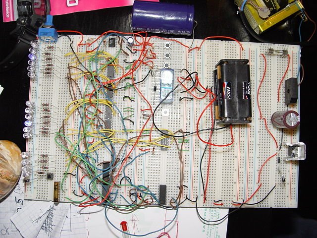
This post is meant to describe the behaviour of electronic circuits and systems. Electronics is a practical subject, so it will be best if the circuits can be tried out and check that they behave in the way described here. Only then will you truly understand the ideas in this post.
Electronic devices perform a vast range of tasks. For example, an electronic system in washing machines allows different types of material to be washed at the right temperature for the right length of time. The system controls water flow into and out of the machine, and heats the water if necessary. It also controls the rinsing and spinning.
As another example, some car radios tune themselves automatically to the strongest signal. Though the driver may not know it is happening, on a long journey, the radio retunes as the car travels between the range of one transmitter and the next. This ensures that the sound output remains as clear as possible.
In this chapter, I will delve into the principles of some of the most useful electronic circuits and systems.
ELECTRONIC SYSTEMS: INPUT, PROCESS AND OUTPUT
Any electronic system can be broken down into three parts namely input, process, and output. Electronic systems respond to input signals. A signal is something that varies with time and carries information. For example, some of the signals we human beings respond to are changes in temperature or light intensity, changes in sound level or the weight of a bag of sugar. These signals could also apply to electronic systems.
The input block converts the input signal – the information – into an electronic signal. This will be a voltage which changes to reflect the changing information. The electronic signal is passed into the process block. For the time being, I will simply say that this block processes the signal. The rest of this chapter describes some different types of process device.
The signal coming out of the process block is still an electronic signal but it has been changed, that is, it has been processed. The last block, the output block, responds to this processed electronic signal and changes it into some other form – such as a sound or light signal, or perhaps it turns a motor on or off.
The input and output blocks use devices that convert signals from one form to another. These are called transducers.
TRANSDUCERS
Transducers can be divided into input transducers and output transducers. Input transducers are devices that convert some physical quantity, such as temperature or light level, into a voltage or some other electrical quantity. Input transducers are sometimes referred to as sensors.
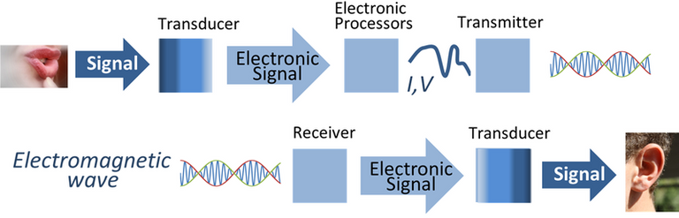
A microphone converts the changes in air pressure of sound into a changing voltage. A light-dependent resistor responds to changes in light intensity by changing its resistance. This change of resistance can be used in a simple circuit to produce a changing voltage.
Output transducers change electronic signals back into some physical quantity. For example, a loudspeaker converts an electronic signal into changes in air pressure – that is, sound.
Electronic systems can be divided into two kinds, although there are many examples where they are used together to make useful systems. These two parts are digital systems and analogue (or linear) systems.
DIGITAL SYSTEMS
Digital systems process digital signals. A digital signal is one which has discrete values (that is, separate as opposed to continuous, possibly varying values). A switch produces a digital signal. The switch is either open or closed, so the voltage output of the circuit will be either 0 V or 5 V, which is the usual voltage range of the power supply. In simple digital systems, there are only two possible signal states. These two states are called low and high.
Some circuits are designed to make digital signals. An astable produces a square wave – it has a frequency and amplitude just like the sine wave more typical of alternating signals, but the signal alternates sharply between a high and low value.
The square wave is a digital signal that changes at a regular rate. If the period (time for one cycle) is constant, circuits like this can be used for timing.
DECISION CIRCUITS – LOGIC GATES AND PROGRAMMABLE MICROCHIPS
Most new cars have an audible alarm that warns the driver that the lights are on when the car door is opened. The electronic system that does this uses two inputs:
- A push-button switch which is closed when the door is opened.
- The light switch – off when the lights are off and on when the lights are on!
There is one output which activates the buzzer that produces the audible warning. The table shows the possible combinations in a truth table.
The design of a system that behaves as described in the truth table is quite simple if we use one of a group of very useful digital circuits called logic gates.
These are simple electronic elements which make decisions about an output based on one or more inputs. The simplest logic gate, the NOT gate or inverter, has only one input; other logic gates have two or more inputs.
In the block diagram of a slightly more complex system, which controls the programmes of a washing machine. At each point in a programme, the control system has to make a decision. For example, there are only some conditions which will turn the washing machine motor on, and these are summarised in the table below.
A table showing the combinations of switches for the lights-on alarm
| Light switch | Door switch | Audible warning |
|---|---|---|
| Off | open | Off |
| Off | closed | Off |
| On | open | Off |
| On | closed | On |
The motor switches on only when the door is closed and when the temperature of the water is higher than 55 °C (2 and 3 in the table), or when the dial is set to allow the load to be washed at temperatures of less than 55 °C, in which case the wash switch is on (1 in the table).
A table showing the combinations of conditions for the motor of a washing machine
| Water temp. Sensor | Wash switch | Door | Motor |
|---|---|---|---|
| <55°C | Off | Open | OFF |
| <55°C | Off | Closed | OFF |
| <55°C | On | Open | OFF |
| <55°C | On | Closed | ON [1] |
| >55°C | Off | Open | OFF |
| >55°C | Off | Closed | ON [2] |
| >55°C | On | Open | OFF |
| >55°C | On | Closed | ON [3] |
This design problem could also be solved using a combination of logic gates but today, It is far more likely to be solved using programmable microchips or PICs. PIC stands for Peripheral Interface Controller. It is a simple computer equipped with inputs and outputs, memory and microprocessor, all contained on a single microchip. PICs are very adaptable – they will do what the program tells them to do. The inputs and outputs can be digital or analogue.
The advantage of using a PIC in a washing machine system is that it can be programmed to carry out a variety of different washing cycles, which can be simply selected by a switch.
Logic gates and truth tables
The inputs and outputs to and from logic gates will depend on the power supply, but are often 0 V or 5 V. An input or output at OV 1s described as ‘low’ and an input or output at or near 5 V is ‘high’. The low and high voltages at inputs or outputs are given the binary codes 0 and 1. Truth tables using these digits summarise the behaviour of logic gates. The figure below shows the circuit symbol for a useful logic gate.

ANALOGUE SYSTEMS
Many electronic circuits are designed to respond to signals that change over a wide range of values, like the varying temperature of the water in the washing machine. These are known as analogue systems. A circuit can be used as a temperature-sensing input board. The thermistor is joined to a variable resistor to make up a potential divider. The voltage at the output of this circuit will change with temperature. The output voltage range can be adjusted by changing the variable resistor since the variable resistor changes the sensitivity of the circuit.
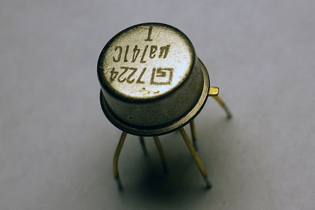
THE OPERATIONAL AMPLIFIER
There is a family of amplifiers available in chip form (that is, as integrated circuits), which are very useful in all sorts of applications. These are called operational amplifiers. It will be useful first to look at the properties of a simple amplifier; which I will shed more light on in my next post.
Till then, I remain my humble self; @emperorhassy.
REFERENCES
https://www.sciencedirect.com/book/9780080108889/physical-electronics
http://elibrary.bsu.az/books_250/N_220.pdf
https://www.mccormick.northwestern.edu/electrical-computer/academics/courses/descriptions/250.html
https://slideplayer.com/slide/8945195/
https://www.electronics-tutorials.ws/io/io_1.html
https://en.wikipedia.org/wiki/Transducer
https://www.nyu.edu/classes/bello/FMT_files/7_digital.pdf
http://www.digitaltechnologieshub.edu.au/teachers/topics/digital-systems
https://www.oreilly.com/library/view/fundamentals-of-digital/9781118969304/9781118969304c01.xhtml#:~:text=Digital%20systems%20are%20designed%20to,communicate%20information%20in%20digital%20form.&text=The%20digital%20computer%2C%20more%20commonly,or%20more%20precisely%2C%20binary%20form.
https://www.allaboutcircuits.com/worksheets/programmable-logic-technology/
https://www.electronics-tutorials.ws/logic/logic_1.html
https://www.electronics-tutorials.ws/boolean/bool_7.html
http://www.ee.surrey.ac.uk/Projects/CAL/digital-logic/gatesfunc/index.html
https://electronicsclub.info/analogue.htm
https://www.soundonsound.com/reviews/analogue-systems-rs-modular
https://en.wikipedia.org/wiki/Operational_amplifier
https://www.electronics-tutorials.ws/opamp/opamp_1.html
Thanks for your contribution to the STEMsocial community. Feel free to join us on discord to get to know the rest of us!
Please consider supporting our funding proposal, approving our witness (@stem.witness) or delegating to the @stemsocial account (for some ROI).
Thanks for using the STEMsocial app
and including @stemsocial as a beneficiary, which give you stronger support.