ESP
🔌 Circuito Paralelo RLC: Análisis de Comportamiento y Respuesta 📈
¡Hola hermosa comunidad Hive! Hoy profundizamos en el análisis de un circuito RLC paralelo, una estructura imprescindible en electrónica para aplicaciones como filtros, sintonizadores y osciladores. Comprender estos circuitos es fundamental para avanzar en el estudio y diseño de sistemas electrónicos más complejos. 🚀⚡
Introducción al Circuito Paralelo RLC 📚
Un circuito RLC en paralelo consta de una resistencia (R), un inductor (L) y un condensador (C) conectados en paralelo a una fuente de voltaje. Este tipo de circuito tiene una respuesta dinámica interesante y es útil en una variedad de aplicaciones.
Componentes del circuito 🔧
- Resistencia (R): Disipa energía en forma de calor y se opone al flujo de corriente.
- Inductor (L): Almacena energía en un campo magnético y se opone a cambios rápidos de corriente.
- Condensador (C): Almacena energía en un campo eléctrico y se opone a cambios rápidos de voltaje.
Ecuaciones fundamentales 📝
La ecuación que describe la dinámica de un circuito RLC paralelo es: 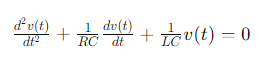
Dónde:
- 𝑣(𝑡) es el voltaje entre los componentes.
- 𝑅 es la resistencia.
- 𝐿 es la inductancia.
- 𝐶 es la capacitancia.
Análisis del Comportamiento del Circuito Paralelo RLC ⏱️
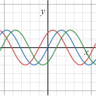
La respuesta del circuito RLC en paralelo también depende del factor de amortiguación (𝜁)
- Sobreamortiguado (𝜁>1): El voltaje vuelve a cero sin oscilar.
- Amortiguado críticamente (𝜁=1): El voltaje vuelve a cero lo más rápido posible sin oscilar.
- Subamortiguado (𝜁<1): El voltaje oscila antes de estabilizarse.
La constante de tiempo (τ) y el factor de amortiguación (ζ) vienen dados por: 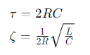
Respuesta del circuito a una excitación escalonada 🚀
*Aplicación de Voltaje: Al aplicar un voltaje 𝑉0 al circuito, la respuesta varía dependiendo de los valores de R, L y C.
- Oscilación y Amortiguación: El comportamiento oscilatorio depende de 𝜁.
- Estabilización: Con el tiempo, el voltaje se estabiliza en un valor determinado por los componentes del circuito.
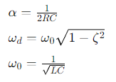
La solución general para el voltaje en un circuito paralelo RLC con búfer insuficiente es:
Dónde:
Ejemplo Práctico de un Circuito Paralelo RLC 🛠️
Consideremos un circuito RLC paralelo con una resistencia de 10 Ω, un inductor de 2𝐻 y un condensador de 0,5𝐹. Supongamos que se aplica un voltaje de 10𝑉.
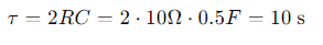
Constante de tiempo (τ):
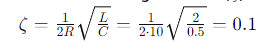
Factor de amortiguación (𝜁):
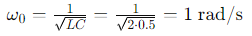
Frecuencia Natural (𝜔0):
📢 ¡Gracias por leer! Manténgase conectado para obtener más contenido educativo 📚
Espero que este post te haya sido útil. Si es así, no olvides dejar un comentario y compartir tus pensamientos o preguntas. 📝
🔔 No te pierdas mis próximos posts donde seguiremos explorando el fascinante mundo de la electrónica y los circuitos. Cada semana, traeré nuevos temas, ejemplos prácticos y recursos para que sigas aprendiendo y mejorando tus habilidades.
🤝 Sígueme en mis redes sociales, donde podrás conectarte con otros entusiastas de la electrónica, hacer preguntas y recibir ayuda en tiempo real. ¡Estamos aquí para ayudarte!
📷 Comparte tus Proyectos: Si has aplicado este conocimiento en tus propios proyectos, ¡nos encantaría verlos! Comparta su progreso y aprenda de otros en nuestra comunidad.
🌟 Mantente en Contacto: Sígueme en mis redes sociales para actualizaciones, contenido exclusivo y más consejos sobre electrónica y circuitos. Tu participación y apoyo son los que hacen que esta comunidad crezca y se enriquezca.
¡Nos estamos leyendo! Hasta entonces, sigue explorando, aprendiendo y compartiendo. ¡Juntos, hacemos que la electrónica sea más accesible y emocionante para todos! 🚀✨
ENG
🔌 RLC Parallel Circuit: Behavior Analysis and Response 📈
Hello beautiful Hive community! Today we delve into the analysis of a parallel RLC circuit, an essential structure in electronics for applications such as filters, tuners and oscillators. Understanding these circuits is essential to advance in the study and design of more complex electronic systems. 🚀⚡
Introduction to the RLC Parallel Circuit 📚
A parallel RLC circuit consists of a resistor (R), an inductor (L), and a capacitor (C) connected in parallel to a voltage source. This type of circuit has an interesting dynamic response and is useful in a variety of applications.
Circuit Components 🔧
- Resistance (R): Dissipates energy in the form of heat and opposes the flow of current.
- Inductor (L): Stores energy in a magnetic field and opposes rapid changes in current.
- Capacitor (C): Stores energy in an electric field and opposes rapid changes in voltage.
Fundamental Equations 📝
The equation that describes the dynamics of a parallel RLC circuit is:
Where:
- 𝑣(𝑡) is the voltage across the components.
- 𝑅 is the resistance.
- 𝐿 is the inductance.
- 𝐶 is the capacitance.
Analysis of the Behavior of the RLC Parallel Circuit ⏱️
The response of the parallel RLC circuit also depends on the damping factor (𝜁)
- Over-damped (𝜁>1): The voltage returns to zero without oscillating.
- Critically damped (𝜁=1): The voltage returns to zero as quickly as possible without oscillating.
- Under-buffered (𝜁<1): The voltage oscillates before stabilizing.
The time constant (τ) and the damping factor (ζ) are given by:
Circuit Response to a Step Excitation 🚀
- Application of Voltage: When applying a voltage 𝑉0 to the circuit, the response varies depending on the values of R, L, and C.
- Oscillation and Damping: Oscillatory behavior depends on 𝜁.
- Stabilization: Over time, the voltage stabilizes at a value determined by the circuit components.
The general solution for the voltage in an underbuffered RLC parallel circuit is: 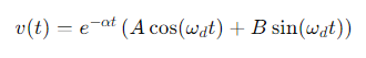
Where:
Practical Example of an RLC Parallel Circuit 🛠️
Let's consider a parallel RLC circuit with a 10Ω resistor, a 2𝐻 inductor, and a 0.5𝐹 capacitor. Suppose a voltage of 10𝑉 is applied.
Time Constant (τ):
Damping Factor (𝜁):
Natural Frequency (𝜔0):
📢 Thanks for reading! Stay Connected for More Educational Content 📚
I hope this post has been useful to you. If so, don't forget to leave a comment and share your thoughts or questions. 📝
🔔 Don't miss my next posts where we will continue exploring the fascinating world of electronics and circuits. Each week, I'll bring new topics, practical examples, and resources to keep you learning and improving your skills.
🤝 Follow me on my social networks, where you can connect with other electronics enthusiasts, ask questions and receive help in real time. We are here to help you!
📷 Share your Projects: If you have applied this knowledge in your own projects, we would love to see them! Share your progress and learn from others in our community.
🌟 Stay in Touch: Follow me on my social networks for updates, exclusive content and more tips on electronics and circuits. Your participation and support are what make this community grow and enrich.
We are reading each other! Until then, keep exploring, learning and sharing. Together, we make electronics more accessible and exciting for everyone! 🚀✨
Nice concept keep it on
Congratulations @profwhitetower! You have completed the following achievement on the Hive blockchain And have been rewarded with New badge(s)
Your next target is to reach 3750 upvotes.
You can view your badges on your board and compare yourself to others in the Ranking
If you no longer want to receive notifications, reply to this comment with the word
STOPCheck out our last posts: