Into the World of Binary System

On this topic, let’s dig deeper into PLC operations, its instructions and I’ll show some of my practical exams that I passed, as promised. When it comes to PLC, 1+1 is not always equal to 2. Being introduced to PLC operations and instructions helps you to understand how its logic works and it’ll show you how 1+1 is equal to 1.
In the world of automation, TRUE or FALSE conditions indicates to a device state being ON or OFF, CLOSED or OPEN, PRESENT or ABSENT, 24 VOLTS or 0 VOLTS. In the PLC, it all reduces or simplify the input to our familiar fundamental element called the binary system, of a 1 or a 0. Usually having a bit ON represents a TRUE condition as OFF is FALSE. Although this is illogical as it may make more point to apply what is called failsafe logic and have an ON bit as a FALSE condition.
Let us set sights again to several simple statements but this time using automation examples.
   •    When the button is pressed AND the door is closed, then the motor turns on.
   •    If the process is done OR the Emergency Stop button signal is NOT on, then the motor turns off.  (An
      example of a failsafe operation as the Emergency Stop button could be pressed or the wire has been disconnected.)
   •    If the tank is full OR the button is pressed AND there are no alarms, then start the process.
It would be easier to program like this but computers more structured and complicated when it comes to its commands. A series of graphical objects have been used for years to represent the logic elements converted to a common ladder logic equivalent easily. These functions are called gates as they operate like gatekeepers for different logic.
Logic Gates
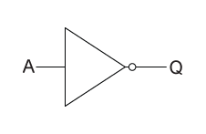
In digital logic, an inverter or NOT gate is a digital logic gate which implements logical negation and has only a single input with simple behavior. If the input is true, then the output will be false and a false input results in a true output.


The NOT function can be implemented on a contact input basically by using a normally-closed contact instead of a normally-open contact. The Output (Q) energizes if the contact is not actuated, and de-energizes when the contact is actuated.
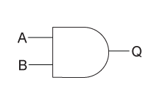
An AND logic gate works with two electrical inputs that when both inputs are switched on, there will be an output. Otherwise, the output will be 0.


If and only if both switch contacts are closed, a path for current exists from wire L1 to the lamp (wire 2) and the lamp energizes only if contact A and contact B are simultaneously actuated.

An OR logic gate also works with two electrical inputs same as AND logic gate. If either input is switched on, the output will be 1 as well. Otherwise the output will be 0.


The lamp will turn on if either contact A or contact B is actuated, because all it takes for the lamp to be energized is to have at least one path for current to pass through from wire L1 to the intersection.
The figure below shows the typical logic gates along with their variations.
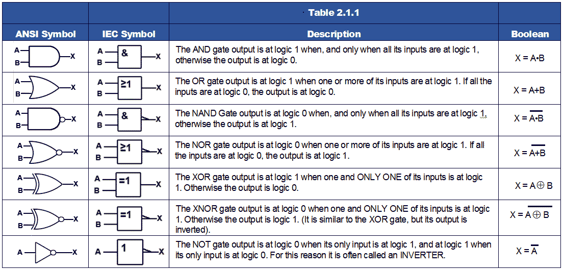
So, must remember that:
- Parallel contacts are logically equivalent to an OR gate.
- Series contacts are logically equivalent to an AND gate.
- Normally closed (N.C.) contacts are logically equivalent to a NOT gate.
- A relay must be used to invert the output of a logic gate function, while simple normally-closed switch contacts are sufficient to represent inverted gate inputs.
Exercise
So now, I'm gonna show you one of the basic operational sequences I've kept on my notes.
Problem: A+ B+ A- B-
First, based on the sequence, identify your inputs and outputs and assign each variable to its designated address. Be careful in tagging and remember that not all binary digits can work according to your preference because some address has its own standard operation.
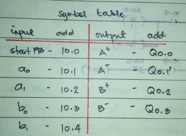
Always remember the basic primary logic gates. Next, I used GRAFCET or SFC (Sequential function chart) which is a graphical programming language used for programmable logic controllers.
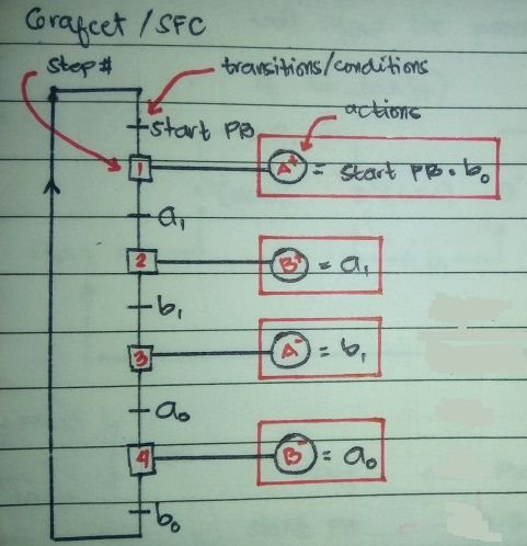
After the GRAFCET where I could clearly see or determine the transitions or conditions and actions on a step-by-step basis. This method prevents me from getting confused when I'll proceed to PLC programming, as shown below:
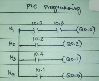
This is just one of the basic sequence and operation and I hope this could help especially to beginners and who are interested to enter the world of industrial processes and control. Stay tuned for more learnings!
very good knowldge
thanks sir ;)