In this article we continue our journey into understanding mobile networks in general, and voice calls in particular.

Source: Pixabay
This post will focus on improving the reader's understanding of a full mobile originated (MO) call setup. The next post will then examine incoming calls, known technically as mobile terminated (MT) calls.
For those who haven't read my previous posts in this series I strongly recommend heading back for my previous post Introduction to Mobile Networks - Voice Calls (Part 1)
For reminder we learned that the a mobile originated call involves the following:
- Caller dials the called party number and initiates the call.
- UE sets up logical channels with the BTS/BSC for transmission of signalling and user traffic.
- BSC passes on call setup request to MSC/VLR.
- MSC/VLR checks caller is authorized to place the call the called party.
- MSC forwards the call establishment to the called party's network gateway MSC.
- Gateway MSC initiates MT call to called party
- Call progresses to the alerting state. Usually this means the called party's handset is ringing.
- The called party's network indicates that the call has been answered.
- Audio flows as user traffic between the caller's handset and the called party's network.
There are many steps involved in connecting a voice call and in this post only essential mechanisms are shown for simplification reasons.
Instead of showing you a very long sequence diagram I will break down the procedure in manageable chunks.
Bear in mind that there can be some slight variations of the described procedures from network to network.
In any case the general principles outlined in this post remain consistent across networks.
Let's now examine each phase in details.
The subscriber initiates the call by entering the called party number ISDN number.
Assuming that the UE is currently in idle mode (not on a radio channel), the handset sends a
Channel Required message on the random access control channel (RACCH) indicating that the requested resource is for a voice call.
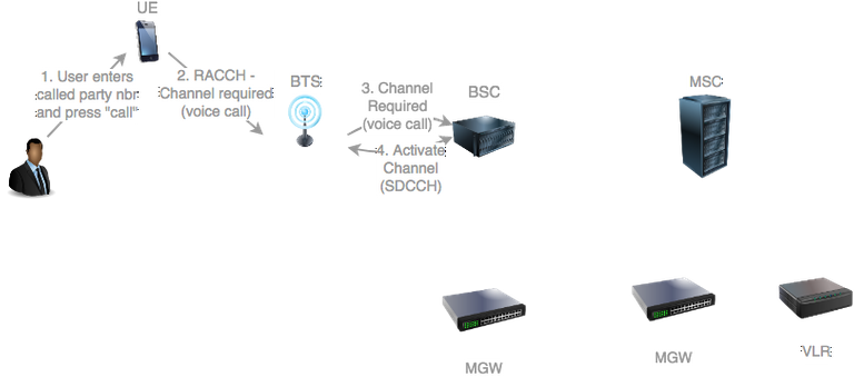
Source: original illustration for Steemit
The call starts when the subscriber dials the number of the called party, either through the handset dialer or through the address book.
If currently idle (not on a radio channel), the UE needs to request assignment of a logical channel.
It does so by sending a Channel Required on the Radmon Access Control Channel (RACCH).
The Channel Required indicates that the channel is for a voice call.
The BSC receives the Channel Required and finds an unused signalling dedicated control channel (SDCCH).
The BSC requests the BTS to activate the SDCCH identified by the local channel number. This procedure was already described in a previous post
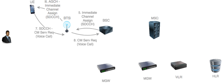
Source: original illustration for Steemit
The BSC now sends and Immediate Assignment Request to the UE specifying the channel number of the SDCCH it should now use for progressing the progressing the procedure.
The Immediate Assignment Request is sent to the UE by the BTS on the Access Grant Channel (AGCH).
The UE cannot straight away place the call. It must first request authorization from its currently attached VLR.
It does this by sending over the SDCCH a Connection Management (CM) Service Request indicating that the desired service is a voice call.
The CM Service Request is received by the BSC.
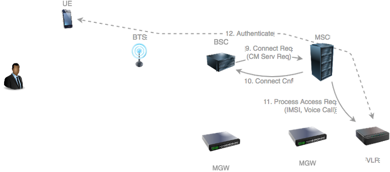
Source: original illustration for Steemit
The BSC initiates a new connection with the MSC and forwards the CM Service Request.
The MSC acknowledges the new connection with a Connection Confirm.
The MSC now notifies the VLR that the subscriber is requesting a particular type of access to the network by sending a Process Access Request message specifying the IMSI of the subscriber the desired service type (voice call).
At this stage the VLR may initiate the authentication procedure previously described here.
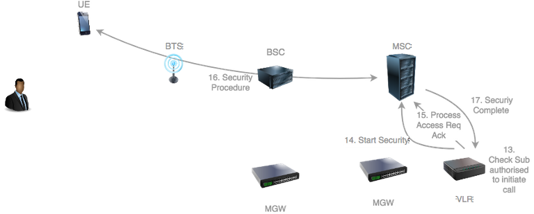
Source: original illustration for Steemit
The VLR checks that the subscriber is authorised to initiate voice calls.
The VLR indicates to the MSC that the security procedure should be initiated with the UE to secure the radio link.
It then indicates acceptance to the MSC that the service is accepted by sending a Process Access Acknowledgment.
The MSC then initiates the security procedure described here.
The MSC notifies to the VLR that the security procedure is complete.
Source: original illustration for Steemit
The security procedure initiation from the network has indicated to the UE that the service request has been accepted. It can now initiate the call.
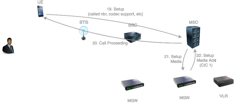
The UE sends a Setup message to the network indicating various information such as the ISDN number of the called party, voice codec capabilities and various other parameters which can be used by the network later on during the call.
The MSC receives the Setup and sends back a Call Proceeding to the UE to indicate that the call is now being processed.
The MSC needs to start preparing the user plane required for transporting the audio traffic.
The exact protocol used to program the media gateway (MGW) is not standardized in 3gPP.
A voice call in a 2G/3G core network takes place over an SS7 network, which was described in my previous post.
In SS7 each endpoint handling voice traffic is identified by a number called a Circuit Identity Code (CIC).
When the MSC requests the MGW to prepare an endpoint for handling the audio traffic, it specifies the information required to handle the audio such as the selected voice codec.
The MGW prepares the endpoint and then returns the associated CIC to the MSC.
Source: original illustration for Steemit
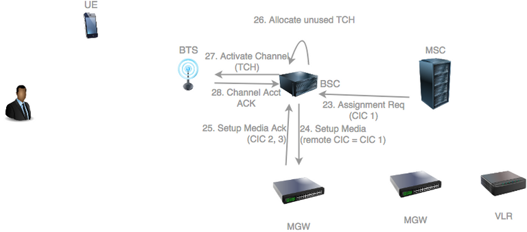
The MSC sends to the BSC an Assignment Request to indicate that the BSC should now proceed with setting up the user plane for the audio traffic and transfer the UE to a radio channel suitable for voice calls. In the process it supplies the CIC assigned by its own MGW for the call.
The BSC requests its MGW to setup two media endpoints: one towards the network (supplying the CIC supplied by the MSC to the BSC), and one towards the RAN.
The MGW allocates both UP endpoints and sends back both allocated CICs to the BSC.
The BSC now needs to allocate a traffic channel (TCH) for the call. A TCH is a type of logical channel suitable for a voice call which reserves a fixed amount of bandwidth (typically 16kbs).
The BSC requests the BTS to activate the allocated TCH.
The BTS activates the TCH and sends back a Channel Activation Acknowledgement.
Source: original illustration for Steemit
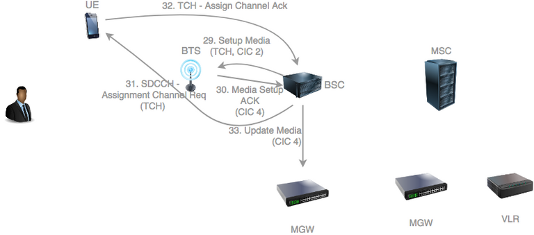
The BSC now needs to indicate to request the BTS to setup the required terrestrial resources for transfer of the audio traffic. It specifies to the BTS the CIC allocated by its MGW towards the RAN.
The BTS allocates terrestrial resources for the audio and sends back an acknowledgement to the BSC with the CIC that will handle downlink (network to UE) audio traffic.
The BSC now requests the UE to stop using the SDCCH and switch to the TCH logical channel. It does so by sending an Assignment Request.
The UE switches to the TCH and sends back an Assignment Acknowledgement.
The BSC now needs to update its MGW with the CIC assigned by the BTS. This ensures that the MGW will now sends audio traffic to that CIC in the downlink direction.
Source: original illustration for Steemit
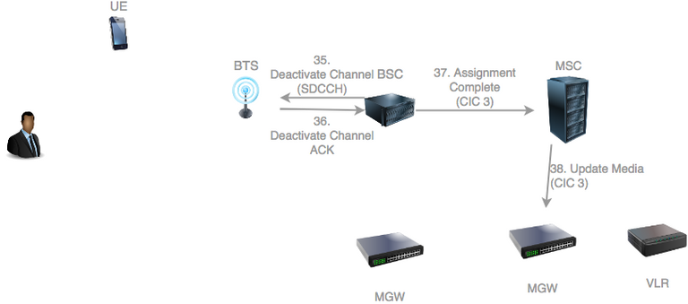
The BSC can now deactivate the SDDCH which is no longer in use. It does so by sending a Deactivate Channel Request.
The BTS deactivates the SDCCH and sends back a Deactivate Channel Acknowledgment.
The BSC notifies the MSC that all resources are ready for the call by sending an Assignment Complete. It specifies the CIC assigned by its MGW towards the network.
The MSC needs to update its MGW with the CIC used by the BSC in the downlink direction.
Source: original illustration for Steemit
All resources in the operator's core network are now ready.
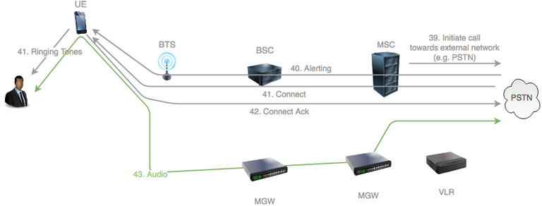
The MSC forwards the call to an external network, such as the Public Switched Telephony Network (PSTN), towards the called party. How the call is routed was discussed in this series' previous post.
At some stage the called party's handset will starting ringing and the network will send an Alerting message to the calling UE.
When this happens the caller can start hearing ringing tones.
The called party then answers the call and this results in a Connect message sent to the caller.
The caller then sends back a Connect Acknowledgement.
The call is now fully connected and audio flows in both directions as indicated by the green arrow.
What Next?
The reader should now have a fair understanding of mobile originated calls and how network resources are assigned for the audio traffic.
In the next post we will concentrate on the mobile terminated (MT) leg of the call.
That is, how the called is received by the home network of the called party and routed the UE.
Acronyms and Concepts
| Acronym | Meaning | Description |
|---|---|---|
| AMR | Adaptive Multi-Rate | Speech codec officially adopted by 3gPP in 1999 |
| CIC | Circuit Identification Code | A numerical value indicating an SS7 endpoint capable of processing an audio stream |
| CP | Control Plane | Medium carrying signalling traffic |
| HLR | Home Location Register | Stores all subscriber information such as IMSI, access and service rights, location information, etc. |
| IMSI | International Mobile Subscriber Identity | 15 digits number uniquely identifying a mobile network subscriber across all providers |
| MGW | Media Gateway | A network entity mainly responsible for switching and transcoding audio user traffic |
| MO call | Mobile Orginated call | Call places from a UE |
| MSC | Mobile Switching Centre | Responsible for servicing all CS application procedures (mobility, messaging, voice calls, etc), switching calls with external telephony networks and forwarding SMSs to Short Message Service Centres (SM-SC) |
| MT call | Mobile Terminated call | Call received by a UE |
| PLMN | Public Land Mobile Network | An operator providing mobile telecommunication services |
| SDCCH | Stand-alone Dedicated Control Channel | A type of logical channel used for signalling traffic |
| SIM | Subscriber Identity Module | A type of UICC fitted within mobile network terminals (e.g. handsets). Responsible for storing important and sensitive information and capable of processing instructions, including authentication algorithms |
| SS7 | signalling System No. 7 | Network infrastructure in legacy telephone networks |
| TCH | Traffic Channel | Logical channel used for carrying voice audio traffic |
| UE | User Equipment | Terminal used by the subscriber to access the mobile network, such as smartphone, modem, IoT device, etc. |
| UP | User Plane | Media carrying user traffic |
| VLR | Visitor Location Register | Stores key information about all subscribers attached the the group of cells that it manages. |
References
- Mobile Application Part (MAP) specification (3GPP TS 29.002)
- Mobile-services Switching Centre - Base Station system (MSC-BSS) Interface Layer 3 Specification (3GPP TS 08.08)
- Basic call handling; Technical realization (3GPP TS 23.018)
Previous Posts in this Series
Introduction to Mobile Networks
The GSM CS Architecture
GSM CS Attachment
Security in 2G (GSM) Networks
3G (UMTS) Authentication
Voice Calls - Part 1
As always do not hesitate to leave comments with your questions and I will make sure to reply with the best possible answers.
So I'm assuming that the Stingray equipment (and other scammers or interception equipment) somehow mimics the BTS/BCS segment of the communication chain?
Yes I would think so, but probably only based on 2G technology.
The thing with 2G is that authentication is not required and thus handsets can be fooled in attaching without authentication to a rogue 2G base station.
The attacker can then service voice calls and SMSs without the knowledge of the phone user.
Note that this is currently not possible on 3G and 4G because handsets are not allowed to attach without authenticating the network. From the authentication procedure session keys are derived which are used to secure all traffic between the phone and the network.
What may be possible for the attacker is to force the UE to attach to the rogue 2G base station (hence no authentication required) by interfering with the normal operator's 3G and 4G radio transmissions.
Difficult but not impossible for an organization with strong technical means.