Hallo Elektronikfreunde.
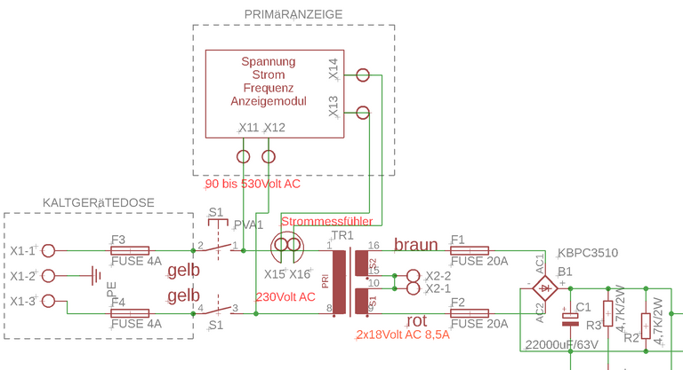
Wie versprochen der Übersichtsschaltplan:
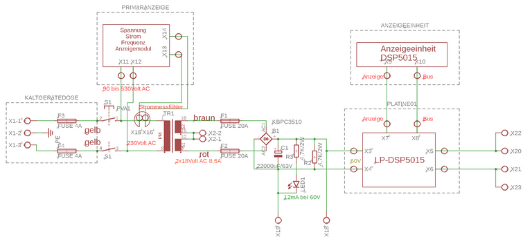
Wie man sehen kann ist das Ganze nicht sehr Umfangreich. Die meisten Komponenten sind käuflich zu erwerbende Fertigmodule. Die Herausforderung besteht in der Verdrahtung, der Gleichrichtung, und in der Gestaltung des Gerätes.
Jetzt ein Sicherheitshinweis: Wer sich im Umgang mit Netzspannung nicht auskennt sollte Arbeiten die mit Netzspannung zu tun haben dem Fachmann überlassen!! Alle Leitungen die mit Netzspannung zu tun haben, also alle Leitungen auf der Primärseite des Trafos, sind so auszuführen das ein berühren nicht möglich ist. Das bedeutet keine blanken Kontakte, bitte Schrumpfschlauch verwenden! Alle Gehäuseteile sind mit dem PE-Leiter zu verbinden. Das ist im Schaltplan der Kontakt X1-2.
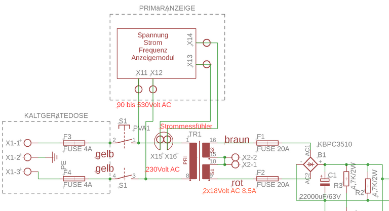
Die drei X1 Kontakte mit der Sicherung stellen die Kaltgerätesteckdose dar.
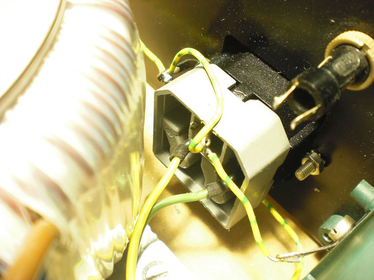
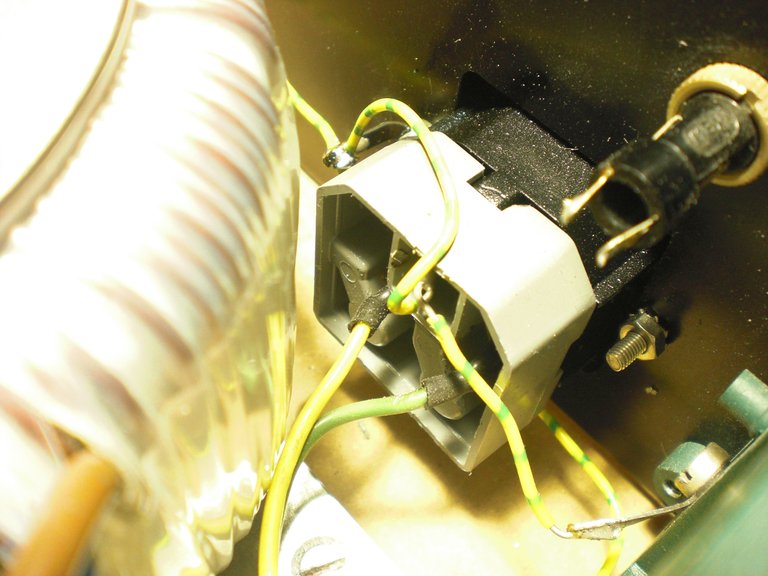
Die Kaltgerätesteckdose von Innen. Gut zu sehen die Schutzleiter gelb - grün.
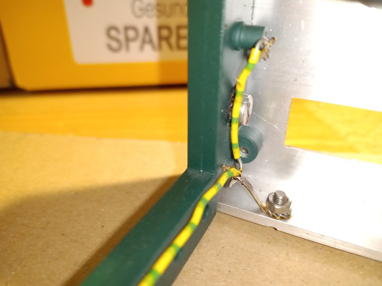
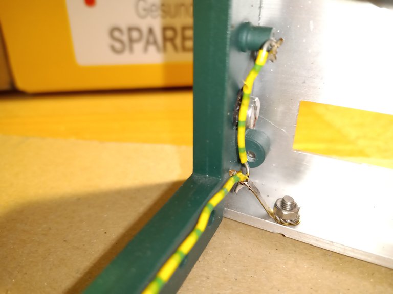
Hier ebenfalls der Schutzleiter, verbunden mit Seitenteil und Vorderfront.
In den Quadratischen Ausschnitt an der Vorderfront gehört ein Netzschalter mit dem ungewöhnlichem Einbaumaß von 34,2 x 12,6mm.
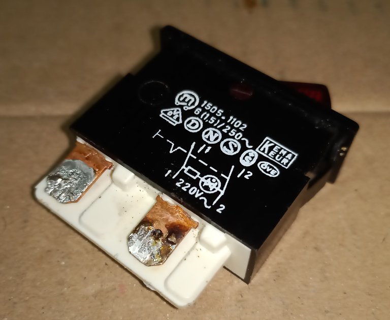
Leider wurde der Originalschalter eingelötet, statt Steckkontakte zu benutzen. Beim auslöten muss die Lötwärme den Schalter beschädigt haben. Leider ist im Internet kaum Ersatz in der benötigten Größe zu finden. Alle heutigen Wippschalter haben kleinere Einbaumaße.
Ein Problem für mich, denn kleiner kann ich den Frontplattenausschnitt nicht machen.
Hier auf der 230Volt-Seite erstmal Pause.
Fortsetzung folgt …….
Google translator
part 3
Hello electronics friends.
As promised, the overview circuit diagram:
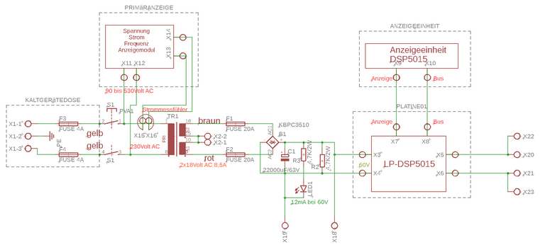
As you can see, the whole thing is not very extensive. Most components are ready-to-buy modules. The challenge is the wiring, the rectification, and the design of the device.
Now a safety note: Anyone who is not familiar with mains voltage should leave work related to mains voltage to the specialist
!! All lines that have to do with mains voltage, i.e. all lines on the primary side of the transformer, must be designed so that touching is not possible. That means no bare contacts, please use shrink tubing! All housing parts are to be connected to the PE conductor. This is contact X1-2 in the circuit diagram.
The three X1 contacts with the fuse represent the IEC socket.
The IEC socket from the inside. The protective conductors yellow - green are clearly visible.
Here also the protective conductor, connected to the side part and front.
In the square cut-out on the front is a power switch with the unusual installation dimensions of 34.2 x 12.6mm.
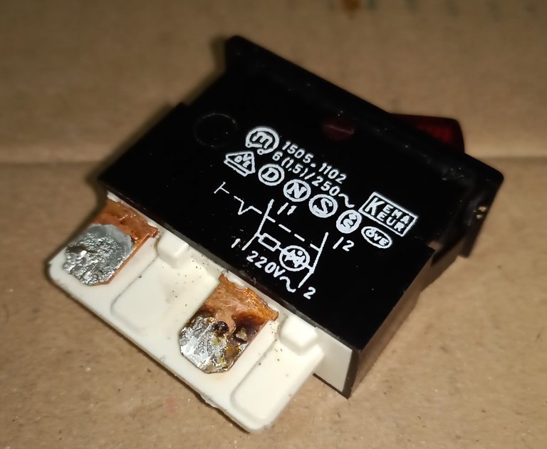
Unfortunately, the original switch was soldered in instead of using plug contacts. The soldering heat must have damaged the switch when unsoldering. Unfortunately there is hardly any replacement in the required size on the Internet. All rocker switches today have smaller installation dimensions.
A problem for me, because I can not make the front panel cutout smaller.
Here a break on the 230Volt side.
Sequel follows …….
