Introduction
The typical magnetic loop antenna is often very large. One common configuration is a one meter diameter loop of one or more turns. I have seen some versions that are made from transmission line cables with the insulation braid broken to create an electrostatic shield. I saw one that has four turns of copper tubing mounted on a plate with an amplifier underneath it. There are a number of circuits published on the Internet with images of output spectrums over the various ranges designed with very high gain and low noise specifically for this kind of antenna.
The tradition designs consume huge amounts of space and are difficult to install. They are susceptible to high winds and severe weather. It is impossible to conceal them. Some of the small ones that are wound on ferrite rods actually do not have very high sensitivity and exhibit limited gain. I saw one version that had multiple ferrite rods in a bundle stuffed into a PVC pipe over which the coil as wound. In all of these versions, it is common to trade off bandwidth for gain to obtain reasonable performance.
This Super Elf antenna covers the low RF radio bands from ELF, SLF, ULF, to VLF ranges. I usually just refer to it as the Super ELF antenna for convenience. It was specially designed with a proprietary composite magnetic core that allows it to be dramatically reduced in size. This antenna is not simply wound over a ferrite rod as is commonly practiced.
Antenna Specifications
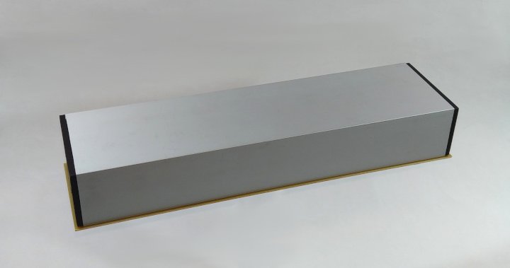
Mechanical Specifications:
Length ……………. 290 mm
Width ……………. 77 mm
Height ……………. 47 mm
A BNC Output Connector and a 4 pin power connector are on the bottom plate.
It is enclosed in an aluminum housing to shield the antenna from electrostatic interference. The power and transmission cable connectors are on the bottom to prevent water and moister from leaking into the antenna enclosure. The entire internal structure is embedded in epoxy to protect it from the environment.

Electrical Specifications:
Input Supply Voltage ………. +/- 9Vdc to +/- 15Vdc
Bandwidth ………………….. 1 Hz to 30 kHz
Performance
A dual +/- V power supply, not included, must be installed near the antenna to supply power to the preamp. Placing a preamp right at the antenna output reduces the over all noise factor. Any amplifier added later on far from the antenna and at the end of a long transmission line will not introduce much more noise as is commonly practiced. I have operated the antenna off of a pair of 9 Volt batteries for a couple of weeks continuously before having to change them.
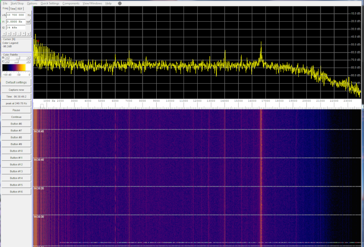
The noise floor of the spectrum shown above is 10 db lower than the 1 meter magnetic loop antenna I have in the lab. The bandwidth gain roll off starting around 18 KHz is cause by the audio amplifier built into the computer mother board. The preamp is nearly flat out to 30 KHz. The signals picked up were buried in the noise in the standard loop. This antenna amplifier combination actually has lower noise and higher gain than the standard magnetic 1 meter loop with the same preamp.
Conclusion
This antenna design was a huge success. It clearly out performed the standard 1 meter magnetic loop antenna with stunning performance. Signals that were buried in the noise floor before are now clearly visible despite the fact that the noise floor is also much lower. There are clearly defined signals that were indistinguishable from the noise before. The method for construction of this antenna can be extended to a larger more sensitive design without sacrificing huge amounts of space to do it. Now, I can watch submarine signals with clarity.