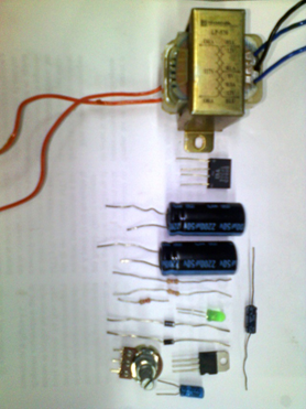
Materials:
Resistances:
- 1 2,4 KΩ a 1/4W (R1)
- 1 220Ω a 1/4W (R2)
- 1 Potentiometer of 5K (P1)
Capacitors:
- 2 2200μF/50V electrolytics (C1, C2)
- 1 10μF/50V electrolytic (C3)
- 1 1μF/35V Tantalum (C4)
Semiconductors:
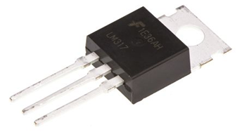
- 1 LM317 voltage regulator (IC1)
- 1 green 5 mm LED (D5)
- 2 Diode 1N4004 (D6, D7)
Various:
- 1 Transformer (T1)
Primary 110 or 220VAC
Secondary 24VAC / 1A
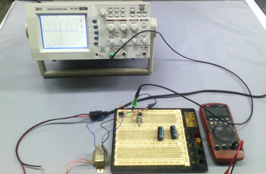
Measuring equipment
- Oscilloscope
- Multimeter
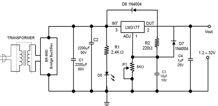
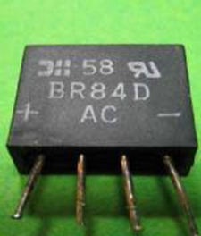
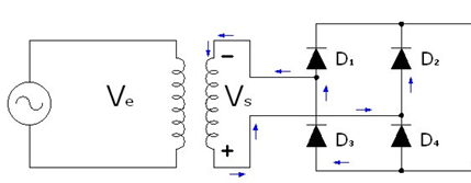
This alternating voltage at the output of the reduction transformer is then rectified with a BR-84D (bridge rectifier).
Source
If you do not have this BR-84D rectifier, you can use the diode configuration shown in the following diagram.
Source
Subsequently, the filtering process is necessary to obtain a direct current voltage. This filtering stage is achieved in capacitors C1 and C2. (Figure 6).

Source
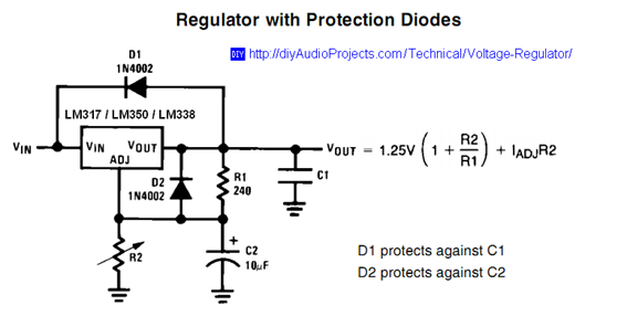
The potentiometer P1 of 5KΩ allows to adjust the output voltage to the desired value. The diodes D6 and D7 protect against peaks of reverse voltage to the regulator.
Source
The equation shown in Figure 8 allows obtaining the desired output voltage value, where the adjustment current (IADJ) has a typical value for LM317 100μA.
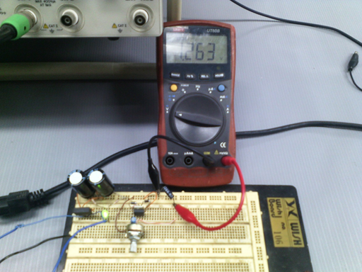
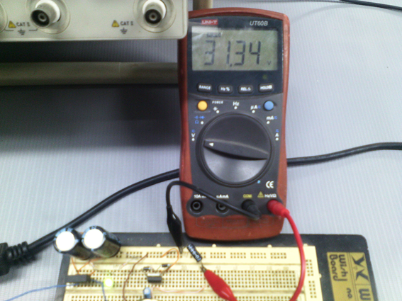
The following pictures shows the minimum voltage and the maximum voltage of the variable voltage source controlled through the potentiometer (Figures 9 and 10).
References:
- Electronica-Digital-Cekit-34-Proyectos-practicos-para-construir
- ROBERT L. BOYLESTAD, LOUIS NASHELSKY. Electronic Devices and Circuit Theory EDITORIAL PEARSON
- http://www.alldatasheet.com/view.jsp?Searchword=LM317T&sField=4
I hope that this publication has given you knowledge about the subject. If you have any questions, please leave your comment and then I will gladly try to clarify them. Thanks for reading my publication.
Excellent post @lorenzor, very useful this type of voltage source for research work. Very interesting the use of the BR-84D rectifier replacing the rectifier diodes Thank you for sharing this information.
Thanks for reading and commenting @wilians. Yes, it is actually more practical to build a variable voltage regulator with the use of the BR-84D. There are designs that use rectifier diodes, everything depends on the available components.
Hi! I am a robot. I just upvoted you! I found similar content that readers might be interested in:
https://wiki.analog.com/university/courses/electronics/text/chapter-6