How to use a homodyne detection technique to detect the resonant peaks of vibrating opto-mechanic oscillators.

Image Credit:-wikimedia

Introduction

Image credit:-wikimedia
This article is different from my usual articles, here I present some of the work I do as part of my degree. I have a system where a laser in sent into an optical cavity and it resonates a membrane similar to that you see in the picture above. The light applied a pressure to the micro meter sized membrane and causes it to oscillate at it's natural frequency. Those oscillations generated by the membrane causes it to modulate the light frequency. Modulation is like putting a frequency inside a frequency like you see in the gif.
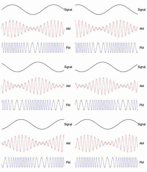
Image credit:-wikimedia
Using the homodyne detection technique the frequency of the membrane oscillation can be detected. The study of such physical processes is important because we can study the effects of cooling micro-sized object, we actually cool the membranes using laser light, then we can reach a quantum regime where membranes maybe entangled quantum mechanically. This type of detection technique is implemented in nearly all areas of science, from physics to chemistry to geology, it's uses are invaluable to scientists.
I should also show you guys the Red Pitaya board, it's what i used to process the signals, it's a fantastic bit of kit for all sorts of signal processing. You can read about it here, and this is what it looks like.

Image Credit:-sharingame.org
I'll show you my results of detecting the membrane resonances and i hope I can teach you something in this article that you find interesting, so let's go ahead.

Homodyne Detection

Image Credit:-wikimedia
Light with some carrier frequency enters the beam splitter (cube), one beam is reflected of a mirror into the detector, the other beam is modulated with some frequency (of the membrane for example) then directed into the detector. The two beams "mix" at the detector, part of the beam that is at the carrier frequency is cancelled by the interference, only the modulated signal is detected.
A homodyne detector uses a single source of light, so that the frequency detected by the photo-diodes will be the same, where "homo" means the same, and "dyne" means power, but we refer to the use of the same frequency. Homodyne detection is a method of extracting information encoded as modulation of the phase and/or frequency of an oscillating signal. By comparing that signal with a standard oscillation that would be identical to the signal. If it carried no information, homodyne signifies a single frequency in contrast to the dual frequencies employed in heterodyne detection. In optical interferometery, homodyne signifies that the reference radiation of the local oscillator is derived from the same source as the signal before the modulating process. The laser is split into two parts, one is the local oscillator, and the other is sent to the system such as an opto-mechanic cavity to be probed. The light is then reflected and mixed with the local oscillator at the detector, this has the advantage of being insensitive to the fluctuations in the frequency of the laser. Usually the reflected light from the cavity will be weak, in which case the nearly steady component of the detector output is a good measure of the instantaneous local oscillator intensity, and can therefore be used to compensate for any fluctuations in the intensity of the laser.
When identifying mechanical modes of an opto-mechanic oscillator, the laser light that impinges in the opto-mechanic membrane will be modulated due to the resonant mode of the oscillator. So the information or frequency of the membrane oscillation will be encoded into the laser light through modulation of the laser light.
The homodyne can be set up such that the light is split by a beam splitter, the two beams traverse different paths. If the beams are out of phase by pi (half a wavelength), and if no modulation occurs then there will be just complete destructive interference, with only noise associated to the "shot noise" of light. But if modulation occurs the homodyne detector will see the beating frequency due to modulation.

Some Background of Noise
When performing signal measurements there is always the presence of some electronic or electromagnetic noise, it is is an unwanted disturbance of an electronic signal, noise occurs at a given frequency and noise level usually given in some units of the Decibel. There is always some noise associated with the electronic devices of a given system, for example a lot of electronics are powered by an AC power source at 50 Hz, which can be seen in the image 1 below. Each peak is associated to harmonics of the 50 Hz alternating current signal. notice how the amplitude of the peak decreases.
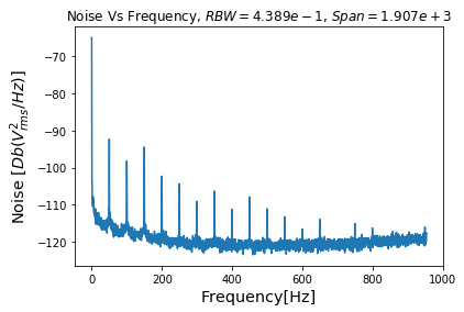
Image 1:-Self-Produced using Python
I used something called a Red Pitaya signal processing unit, which is basically an electronics board that allows me to process electrical signals and analyse the data.
In the next two figures you can see the spectra associated with different noise signals. Figure 2 includes the use of an amplifier to amplify the signal sent to the Red Pitaya, and Figure 3 is the same measurement without an amplifier. You will see that the amplifier increases the power of the signals.
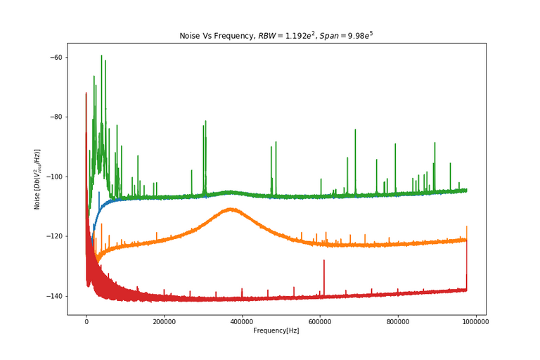
Image 2:-Self-Produced using Python
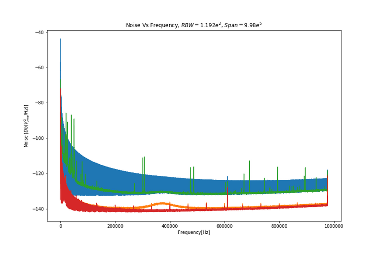
Image 3:-Self-Produced using Python
The Red-curve is associated to the electronic noise in the Red Pitaya (R.P) board, it is seen at high frequencies there is very low level noise; there was no light detection.
The Orange-curve represents the noise of the R.P board connected to the detection system, on both figures it can be seen a large band of noise frequencies between about 200-500 KHz, which is a characteristic of the detection device; no light was detected. Notice how the amplifier increases the signal of the noise when the R.P is connected to the detection system, it increases the noise level.
The Blue-curve is due to the Shot Noise, which is the signal from the homodyne detector when only the laser light is detected without being modulated by the oscillator. In this case the Shot noise is associated to the counting of photons, and due to the nature of light, there is an uncertainty in the position and momentum of the detected light. When the system has been created "perfectly" such that the path length perfectly produce destructive interference then the absolute limit of shot noise is due to the uncertainty in one particle of light, to overcome this limit "squeezing" of light can be performed.
The Green-curve is the actual spectra of the signal detected from the opto-mechanic system, where light impinges on the membrane and causes resonant oscillations, which in turn produces modulation of the laser light. The modulated light is detected by the homodyne detector and provides the frequency peaks for mechanic oscillation modes. Two modes that have been identified can be seen at 301 KHz and 307 KHz. But at the lower end and higher end of the spectrum there are a lot of unwanted peaks due to some noise frequencies within the system. To deal with such noise High and Low Band Pass Filters can be employed to allow only a small range of frequencies to be present in a spectra.

Double Membrane Peaks
I was tasked to extract the peaks associated with the double membrane oscillating modes located at f1= 300,800 Hz and f2= 306,850 Hz, which can be seen in Figure 4 and 5. In order to do this I used the Red Pitaya by passing the input signal through it, i was able to apply and "ac bandwidth" filter to remove lower frequency noise, ensuring the filter allows the mode frequencies pass. Then a modulation frequency was applied that was close to the mode frequencies; this later allowed the spectrum analyser to use a smaller scanning bandwidth (range of individual detection) and span to finely detect the peaks. Then a bandwidth filter was applied to filter out higher frequencies after the modulation occurs. After taking the spectra at small scanning bandwidth and small span the resonant peaks immediately became visible.
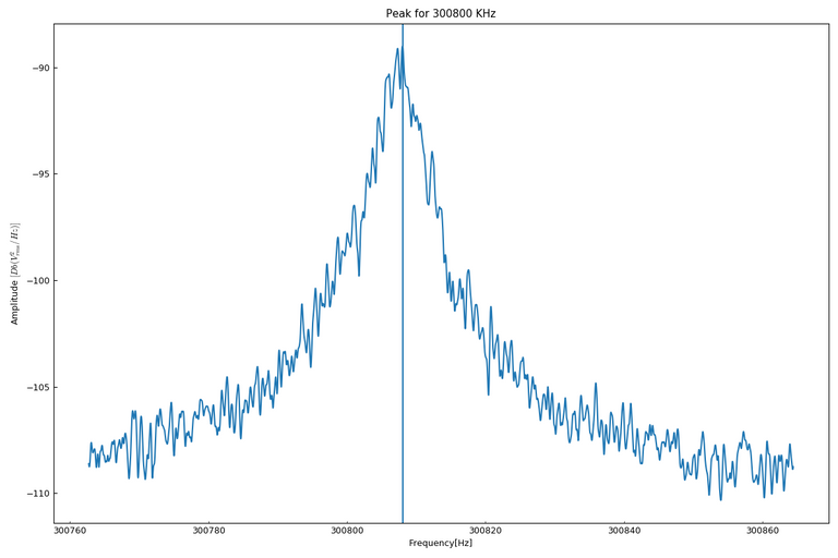
Image 4:-Self-Produced using Python
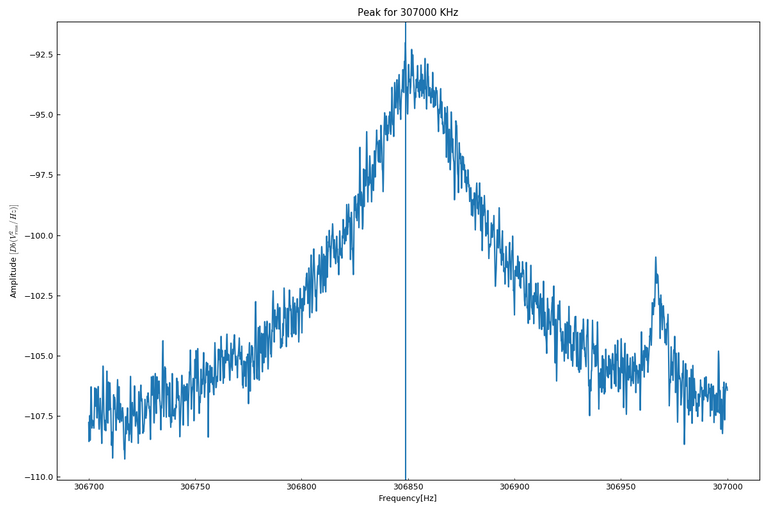
Image 5:-Self-Produced using Python
These are the two peaks associated with the double membrane oscillation inside the cavity. They are lorenztian shaped, and their full-width half-maximum frequency relates to the decay rate of the oscillation of the membranes.

Conclusion
So I was able to detect the resonance peaks after all. They were very close to the theoretic value that was calculated. I was quite happy about that. We had a look at homodyne detection, which is a way of detecting modulated signals in a carrier signal. We had a little look at noise and the noise peaks associated with my experiment. Lot's of noise, a lot of it, this is something that we work hard to avoid especially when working with high precision measurements. Then we say the resonant peaks of the membranes that oscillate inside the cavity.
It's difficult to understand this stuff if you are not familiar with some things, I don't expect people to fully understand but I hope you learnt something and i hope you found it interesting. I could explain everything in great detail, it would take quite a few posts to do that. Follow me, because over time reading my articles my work and topics I write about will all come together and you could learn quite a lot. Until next time folks......
Physics.Benjamin

If you liked this post feel free to UPVOTE, FOLLOW, and RESTEEM.

References:-
Cavity optomechanics
Optical resonators (cavities)
Modulation
Homodyne detection
All images are Creative Commons or public domain, no copyright infringements have occurred.
Quite an educative post. Does your technique in any way similar to Michelson Morley interferometry?
Thank you for that comment. Yes if you are familiar with Michelson Morley interferometry, its the same kind of process going on. But here we are modulating the light in the cavity with a mechanical oscillator that is micro meters in size.
The very kind of posts that brought me to STEM. Things that people do and I have no idea about them, but - those could be used someday in my work. After a minute of googling:
The greatest admire for this kind of posts that can be written only by a handful of people.
Thanks you for that kind comment. I'm glad that it was interesting for you :)
Feel free to check other articles of mine, you may find out more about my type of work.
See you around @alexs1320
Congratulations @physics.benjamin! You have completed some achievement on Steemit and have been rewarded with new badge(s) :
Click on any badge to view your own Board of Honor on SteemitBoard.
To support your work, I also upvoted your post!
For more information about SteemitBoard, click here
If you no longer want to receive notifications, reply to this comment with the word
STOPCavity optomechanical systems present one of the most sensitive routine for detecting mechanical motion using shifts in the optical resonance frequency of the optomechanical resonator.