Have you ever wondered how the current in the wire is measured? If so then read this article.
A magnetic compass, surrounded by a coil of wire, makes an effective but temperamental current-measuring meter. The compass must lie flat on a horizontal surface. We must align the coil with the compass needle under no-current conditions. We must rotate the compass so that the needle points at the “N” on the scale (that is, 0° magnetic azimuth ) under no-current conditions. All of these restrictions add up to quite an annoyance for experimenters working in labs among complex electronic systems. You’ll hardly ever see a compass galvanometer in a professional engineer’s or technician’s workshop.
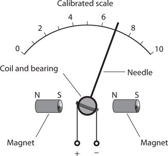
The external magnetic field for a galvanometer need not come from the earth. A permanent magnet, placed near or inside the meter, can provide the necessary magnetic field. A nearby magnet supplies a far stronger magnetic force than does the earth’s magnetic field (or geomagnetic field ), allowing for the construction of a meter that can detect much weaker currents than an old-fashioned galvanometer can. We can orient such a meter in any direction, and slant it any way we want, and it will always work the same way. We can attach the coil directly to the meter pointer, and suspend the pointer from a spring bearing in the field of the magnet. This type of metering scheme, called the D’Arsonval movement , has existed for more than a century. Some metering devices still employ it. Figure 1 illustrates the functional principle of a D’Arsonval current-measuring meter.

Fig 1: Functional drawing of a D’Arsonval movement for measuring current.
(pixabay)
We can fabricate a variation of the D’Arsonval movement by attaching the meter needle to a permanent magnet, and winding the coil in a fixed form around the magnet. Current in the coil produces a magnetic field, which in turn generates a force if the coil and magnet line up correctly with respect to each other. This scheme works okay, but the mass of the permanent magnet results in a slower needle response, and the meter is more prone to overshoot than the true D’Arsonval movement. In overshoot, the inertia of the magnet’s mass, once overcome by the magnetic force, causes the needle to fly past the actual point for the current reading, and then to wag back and forth a couple of times before coming to rest in the right place.
Yet another alternative avails itself: We can substitute an electromagnet in place of the permanent magnet in a D’Arsonval meter assembly. The electromagnet works with the same current that flows in the coil attached to the meter needle. This arrangement gets rid of the need for a massive, permanent magnet inside the meter. It also eliminates the possibility that the meter sensitivity will change over time if the strength of the permanent magnet deteriorates. Such a demise can result from exposure to heat, severe mechanical vibration, or the mere passage of years.
The sensitivity of any D’Arsonval type meter depends on the amount of current needed to produce a certain force inside the device. That force, in turn, depends on the strength of the permanent magnet (if the meter uses a permanent magnet) and the number of turns in the coil. As the strength of the magnet and/or the number of coil turns increases, the amount of current necessary to produce a given force goes down. In an electromagnet type D’Arsonval meter, the combined number of coil turns affects the sensitivity. If we hold the current constant, the force increases in direct proportion to the number of coil turns. The more magnetomotive force the coils produce, the greater the needle deflection for a given amount of current, and the less current it takes to cause a certain amount of needle movement. The most sensitive D’Arsonval current meters can detect a microampere or two. The amount of current for full scale deflection (the needle goes all the way up without banging against the stop pin) can be as little as about 50 μA in commonly available microammeters.
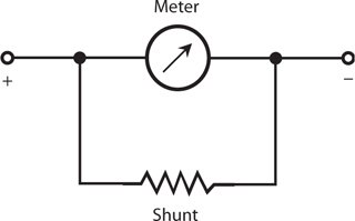
Sometimes we want an ammeter that will allow for a wide range of current measurements. We can’t easily change the full-scale deflection of a meter because that task would require altering the number of coil turns and/or the strength of the magnet inside the assembly. However, all ammeters have a certain amount of internal resistance (even though in a well-designed ammeter, the internal resistance is extremely low; in an ideal one, it would be zero). If we connect a resistor, having the same internal resistance as the meter, in parallel with the meter, the resistor will draw half the current while the meter draws the other half. Then it will take twice the current through the assembly to deflect the meter to full scale, as compared with the meter alone. By choosing a resistor of a specific value, we can increase the full-scale deflection of any ammeter by a fixed, convenient factor, such as 10, or 100, or 1000. The resistor must be able to carry the necessary current without overheating. The resistor might have to deal with practically all of the current flowing through the meter/resistor combination, leaving the meter to carry only 1/10, or 1/100, or 1/1000 of the current. We call a resistor in this application a shunt (Fig. 2 ).

Fig 2: Conversion of Galvanometer into Ammeter
(pixabay)
We can connect a resistor, called a meter shunt, across a current-detecting meter to reduce the meter’s sensitivity.
References:
You just copied the whole of this work
http://slideplayer.com/slide/4158558/
At least you could see how much we love copy and paste here going by the reception (downvotes) you just got.
@steemflagrewards
Posting plagiarized content and also dropping your link onto strangers is not appreciated on Steemit. @steemflagrewards
Congratulations @riemannian! You received a personal award!
You can view your badges on your Steem Board and compare to others on the Steem Ranking
Do not miss the last post from @steemitboard:
Vote for @Steemitboard as a witness to get one more award and increased upvotes!