A fault is said to occur when the desired path of current flow is deviated resulting in the interference with the normal flow of current. Majority of the faults that occur in lines of 132kv and higher are caused by lightning which leads to flash over of insulators.

We have already talked about corona which we described as ionisation of air upon reaching the breakdown of air when the electric field strength gets up to 30kv/cm. Recall that overhead lines are bare and that it is air that insulates one conductor from another.
The cause of the ionisation is the high voltage between a conductor, and the grounded supporting towers provides a path to ground for the charge induced by the lightning stroke. The resulting low impedance of the established ionised path to ground allows the passage of power current from the conductor to ground and through the ground to the grounded neutral of a transformer or generator, thereby completing the circuit.
We can classify faults as symmetrical (balanced) fault or unsymmetrical (unbalanced) fault.
Symmetrical faults are faults on the power system which gives rise to equal fault currents in the lines with 1200 phase displacement. The symmetrical faults occur when all the three conductors of a 3 phase line are brought together simultaneously in a short circuit as depicted in the diagram below.
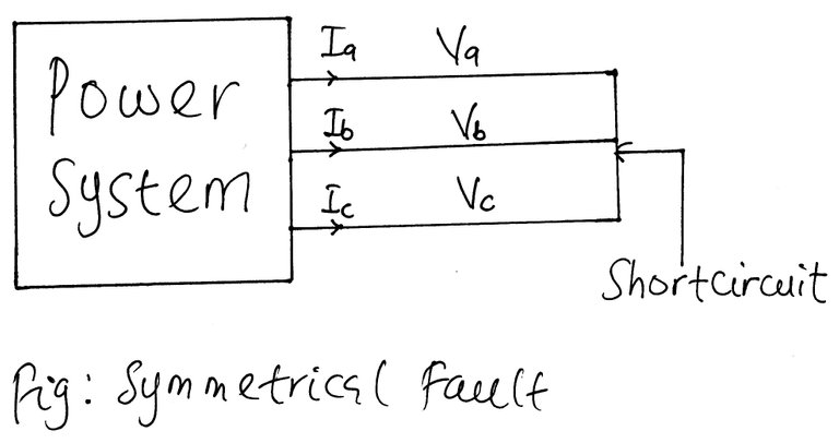
Due to the balanced nature of the fault, we can consider one phase in calculations since conditions in the other two phases will also be similar but only with a change in the phase angle. A symmetrical fault can involve earth as shown in the figure below.
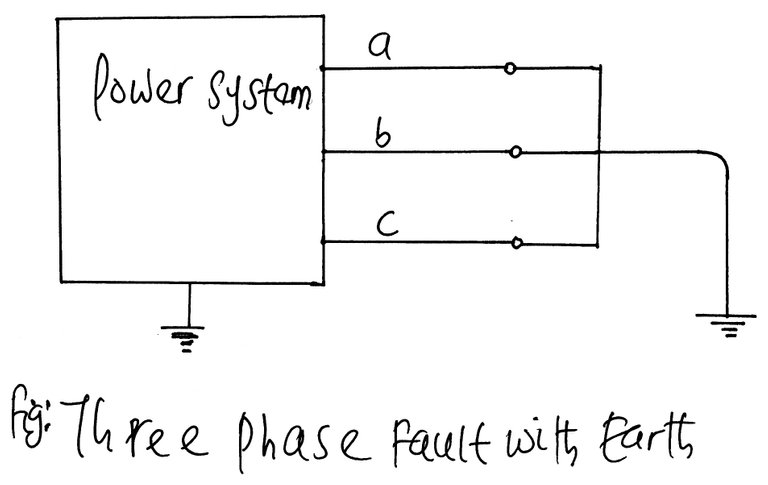
A symmetrical fault can also be clear of earth as shown in the diagram below.
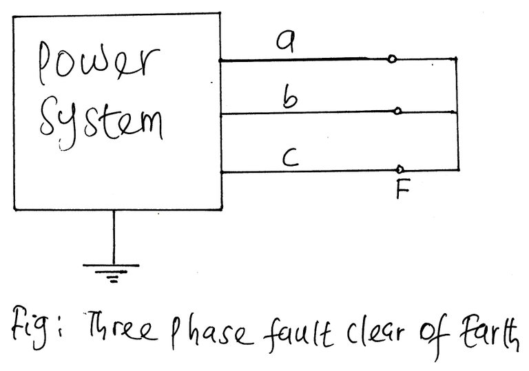
The other classification of unsymmetrical fault (unbalanced fault) are:
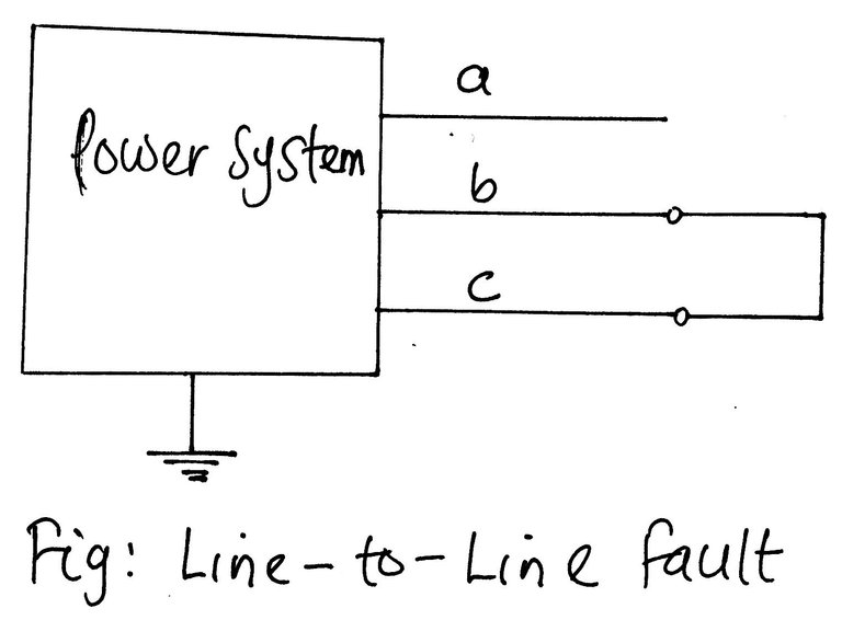
- Line-to-line fault
- Single-line-to-ground fault
- Double line to ground fault.
The line to line fault that does not involve ground is not common as compared to other types of unsymmetrical fault.
Opening of the circuit breaker to isolate the faulted portion of the line from the rest of the system involves the interruption of current in the faulted part of the line from the rest of the system. This is done by making sure that the system neutralises the fault current in the ionised path and allows deionisation to take place.
After an interval of about 20 cycles to allow deionisation to take place, circuit breakers can be reclosed without reestablishing the arc.
Experience in the operation of the transmission line has revealed that the ultra-high speed reclosing breakers successfully reclose on its own after most faults.
The only scenario in which automatic reclosure cannot be achieved is in the event of permanent faults. In the case of permanent fault, reclosure is not guaranteed irrespective of the interval between opening and reclosing.
Permanent lines are caused by lines being on the ground, cracking of insulators as a result of excessive loads like wind and ice load, by permanent damage to towers and by the failure of surge arresters.
Experience has revealed that 80% of transmission line faults are single-line-to-ground fault which arises as a result of flashover of any single line to the tower and ground. Barely 5% of all fault involve all the three phases which we have already describe as symmetrical faults.
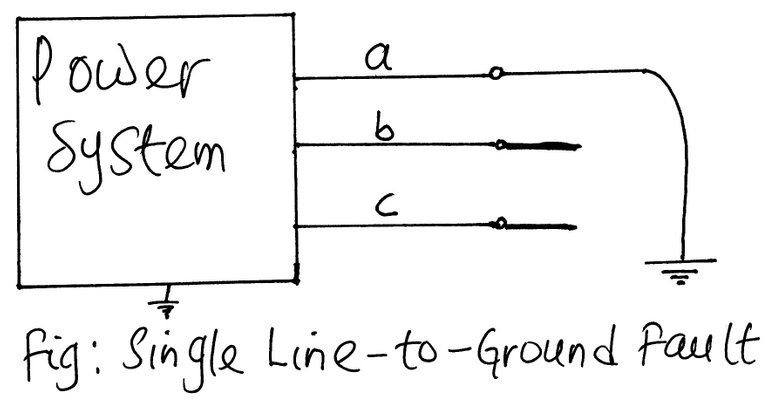
There is also line-to-line fault which does not involve ground and double line to ground fault, just like we mentioned previously.
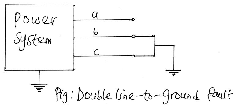
All types of unsymmetrical faults cause an imbalance between the phases and thus, the name unsymmetrical faults.
The current which flows in different part of a power system immediately after the occurrence of a fault is different from those flowing a few cycles later just before the circuit breakers are called upon to open the line on both sides of the fault. And all of these currents differ entirely from the current which would flow under steady-state conditions if the faults were not isolated from the rest of the system by operation of the circuit breakers.
Two of the factors on which the proper selection of circuit breakers are based include; the current flowing immediately after the fault occurs and the current which the breaker must interrupt. In fault analysis, values of these currents are calculated for the different types of faults at various locations in the system. The data obtained from fault calculations also serve to determine the settings of relays which controls the circuit breakers.
The choice of a circuit breaker for a power system requires that the circuit breaker is to continuously carry the normal operating current, be capable of carrying the maximum current albeit momentarily and the current it may have to interrupt at the voltage of the line in which it is placed. All these functions it must have to deliver without malfunctioning.
In summary, the causes of faults are numerous and can originate from any one of the following:
- Lightening
- Heavy winds
- Trees falling across lines
- Vehicles colliding with towers or poles
- Vandalisation
- Small animals entering switchgear
Limitation of Fault Current
The occurrence of short circuit in a power system is accompanied by short circuit current which is attenuated (limited) by the impedance of the system up to the point of fault.
The knowledge of impedance is paramount in the calculation of fault or short circuit current. The method of per unit system which we discussed exhaustively comes to mind and is used to reduce the power system to a much more straightforward form of a system of impedances.
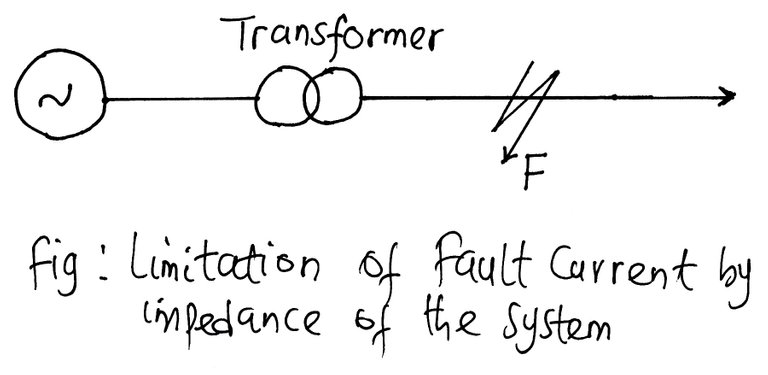
Concerning the figure above, if a fault occurs on the feeder at point F, then the short circuit current from the generating station will have a value limited by the impedance of the line between the generator and the point of fault. The knowledge of impedances of various equipment and circuits in the line of the power system is essential for the determination of short-circuit-current. In many cases, the impedance limiting the fault currents are mainly reactive such as transformers, reactors and generators. Cables and lines are predominantly resistive, but if total reactance in the calculations exceeds three times the resistors, the resistance is usually neglected.
Symmetrical Components and Sequence Network
One of the most popular tools for dealing with unbalanced polyphase circuits is the method of symmetrical components introduced by C.L Fortescue in 1918. Fortescue’s work proves that an unbalanced system of n related phasors can be resolved into n systems of balanced phasors called the symmetrical components of the original phasors. The n phasors of each set of components are equal in length, and the angles between the adjacent phasors of the set are equal.
Method of Symmetrical Component
This method formulates a system of three separate phasor systems which when it is substituted, makes the system somewhat balanced. We have two matrixes, the analysis matrix and the synthesis matrix that is used to solve the problem. A full and proper analysis of unsymmetrical conditions in a three-phase network is made possible by exploiting the facility offered by the symmetrical components method. This method involves the use of two matrices which we shall call analysis and synthesis matrices respectively.
The analysis matrix helps to decompose the phase quantities into symmetrical components or sequence components .

And after we are through with calculation of the fault currents and voltages in terms of the sequence quantities, the synthesis matrix below will be applied to get back the phase current and voltages.

Operator ‘a’
a is an operator defined as follows :
a=1∠1200=-0.5+j0.866
a2=1∠2400=-0.5-j0.866
a3=1∠3600=1+j0
1 + a + a2 = 0
The multiplication of a vector by the operator ‘a’ rotates the vector in the anticlockwise direction by 1200, the magnitude of the vector is, however, unaffected since the magnitude of the operator a is 1.
The analysis of the unsymmetrical faults conditions involves the three sequence networks of the given power system, namely, the positive, negative and zero sequence networks.
Positive sequence
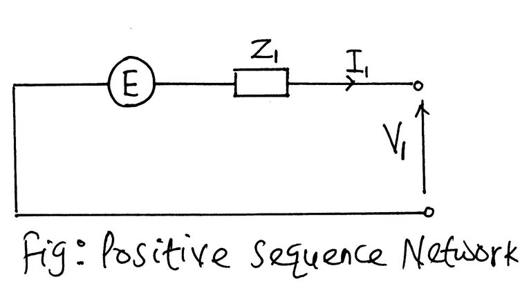
Positive sequence network has a driving point emf E
V1 = E - I1Z1
Negative sequence Network
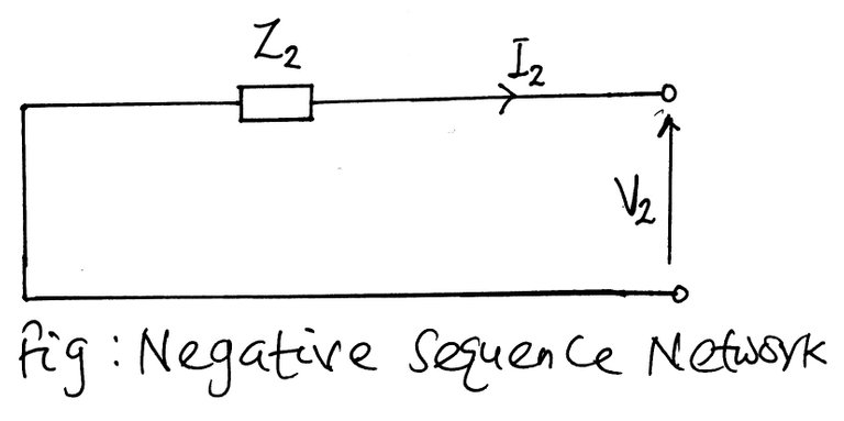
V2 = -I2Z2
Zero sequence Network
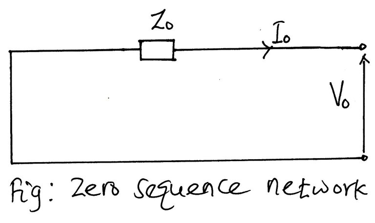
V0 = -I0Z0
E is the pre-fault reference phase voltage at the point of fault and Z1, Z2, and Z0 are the impedances of the positive, negative and zero sequence networks respectively, as measured from the point of fault F.
Like we said earlier, the unsymmetrical faults lead to unbalanced phases, that is different fault current with varying phase angles and if a direct solution is employed, it will prove difficult and rigorous.
The method of symmetrical components substitutes unbalanced phase quantities such as currents and voltages with three separate balanced symmetrical components.
In a three-phase system, the phase sequence is defined as the order in which they pass through a positive maximum. Consider the phasor representation of a three-phase balanced current shown in the figure below
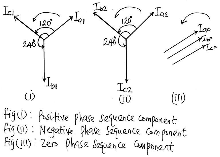
Fig: Representation of symmetrical component
Protective Relays
No matter the level of reliability and security of power system, there is always the likelihood that a fault will occur. Since fault is inevitable, measures must be put in place to eliminate the fault as fast as possible to isolate the faulty part of the network from the healthy part and also to ensure that the system is restored to normalcy in a very short time.
The protection system is comprised of majorly circuit breakers and relays. Protective relays are sensing devices. A relay is a device that can measure or receive a control signal and can initiate sudden preconceived changes in one or more electrical circuits based on the signal it measured or the control signal it received. A relay is an actuator that works in conjunction with the circuit breaker and gives it most of its automatic attributes.
A protective relay, on the other hand, is a relay which response to abnormal conditions in an electrical power system, to control a circuit breaker to isolate the faulty section of the system, with the minimum interruption to service.
The rated current and rated voltage of a relay are the values which its performance is based. They are marked on the relay, and it matches the output of the instrument transformers (voltage and current transformers) or nominal battery voltage with which it is intended to work.
Circuit Breakers
Circuit breakers are mechanical devices designed to close or open contact members, manually or remotely (in the event of a fault or for routine maintenance), thus opening or closing of an electrical circuit under normal or abnormal condition.
Automatic circuit breakers which are used for the protection of electrical circuits comprises of a trip coil which is connected to a relay or other actuator that senses abnormal conditions such as over-current and sends a signal to the trip circuit of the circuit breaker to open circuit breaker.
The circuit breaker works in conjunction with a relay.
The circuit breaker executes the following functions:
- It passes the full load current consistently without malfunctioning
- It can make or break the circuit on no load
- It can make or break the normal operating current
- It can make or break the short circuit current of magnitude within the rating of the circuit breaker
Conclusion
A higher percentage of faults in power system results in short circuit conditions. The aftermath of this condition is the rate of flow of heavy current known as short-circuit current which flows through the equipment, causing considerable damage to the equipment and may lead to a power outage which cuts off supply to the consumers.
Fault analysis and computation are paramount to any power system engineer because it helps to determine the short-circuit current under the fault conditions. The right choice of apparatus and the design arrangement of virtually every equipment in the power system relies upon the information derivable from fault analysis.
We carry out fault studies on power system to determine the values of system voltages and currents during faulted conditions so that protective devices may be set to detect the harmful effect of such contingencies.
The figure involved in fault calculations are usually huge. Fortunately, the concept of per unit, as we discussed in my previous post, helps in scaling down these figures to manageable sizes.
Knowledge of current which might flow when fault occurs is an essential part of the design of a power network. Fault currents are established using computer packages by applying faults at various points (buses) in the network. The magnitudes of the fault currents give the engineer the current setting for the protection to be used and the ratings of the circuit breakers.
The calculation of fault currents can be divided into the two main types:
Faults short-circuiting all the three-phase when the network remains balanced electrically;
Faults other than three-phase short circuits when the network is electrically unbalanced.
To simplify these calculations, we will rely on a robust method for dealing with an unbalanced network, known as the method of the symmetrical component.
The primary objective of fault analysis are:
- To determine the maximum and minimum three-phase short circuit currents;
- To determine the unbalanced fault current for single and double line-to-ground faults, line-to-line faults and sometimes, for open circuit faults
- Investigation of the operation of the protective relays
- Determination of the rated interrupting capacity of breakers;
- To determine fault-current distribution and bus bar voltage level during fault conditions.
This is a test comment, notify @kryzsec on discord if there are any errors please.
Being A SteemStem Member
I find fault analysis to be one of the most interesting parts of power system analysis even though occurrence of fault could mean that some users of the grid may have been thrown into darkness when a fault occurs.
I was waiting for you to break out the equations but it seems you don't want to lose us poor lay people. Your explanation are always so clear that one could prepare for a test on any topic you treat and di very well in the test except if the test is on calculation of certain parameters involved in the topic.
I wonder why line to line fault clear of earth isn't common though.
Thanks for a well detailed post.
Thanks for the time you spent in reading through and your input. Most of the faults in power system involves earth because most of the things that causes short circuit like tree falling across line are not suspended in air but grounded.Also the metal lattice tower is grounded ans as such faults involving earth predominates. Thanks for your time ans comment.
Your diagrammatic description of the different types of fault in Power system made it easy to appreciate. The straightforward analysis of unbalanced fault is difficult but with the introduction of the method of symmetrical components simplifies it and substitutes a balanced fictitious set of currents and voltages which will be eliminated at the end by Synthesis matrix to get back the phase voltages and currents. Thanks for the wonderful piece.
Fault analysis and computation is necessary to establish the magnitude of fault current that will flow in the event of fault so as to know the rating and settings of protective devices that will continuously carry the normal load and fault current. Thanks for such detailed work. Looking forward to your next post.
I appreciate the time you sacrificed in reading the post, and your quick grasp of the topic. Fault can never be completely eliminated from the power system and as such there is need to put protective device in place that will predict and forestall the fault if possible or isolate the faulty part of the system from the healthy part so as to ensure continuity of supply to the healthy section. Many thanks, you are surely a great guy.