I finally found the right screwdriver to get inside one of my handheld transmitters. These can be used to communicate with other people using the same kind of radio, or with local ham radio repeaters. This radio is called the WLN KD-C1, and is a small compact transceiver that can send/receive audio on frequencies ranging from about 400 to 450 MHz (lower is possible but doesn't work well). It puts out about 1 watt of RF power from a small permanent antenna protruding from the top. This lets you directly communicate with people up to a few kilometers away, or much further with use of a repeater.
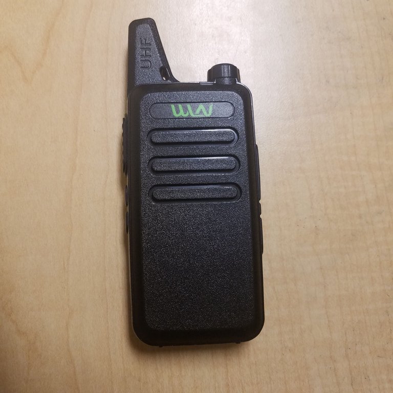
This cost me about $15, and I use it to communicate with people I know on campus via the local repeater. Despite the cost, it's actually got somewhat decent sound quality. Lacking a screen, you have to program the device from a computer (through the audio ports), but it's pretty easy to do, and you can select up to 16 channels/frequencies to use at a time. More interestingly, it can be charged via miniUSB, which means it can be charged by wall plugs, power banks, and laptops. This is the one thing that puts it above my other slightly less cheap UV-5R radio.
It's solidly built, actually. The back plate can be removed to reveal a removable battery (somehow the $15 radio can manage this, but not $800 cell phones...). There are four screws, unfortunately torx-type which makes them a pain to remove if you don't have a screwdriver for them. I just got one today, letting me actually get inside. Even more irritating is the fact that the fifth screw is, of course, hidden under a sticker (you can easily tell by pressing your finger against the sticker and feeling for a spot where it gives, indicating a screw hidden beneath). I was able to remove this screw just by destroying the part above it and not removing the entire sticker, which is nice.
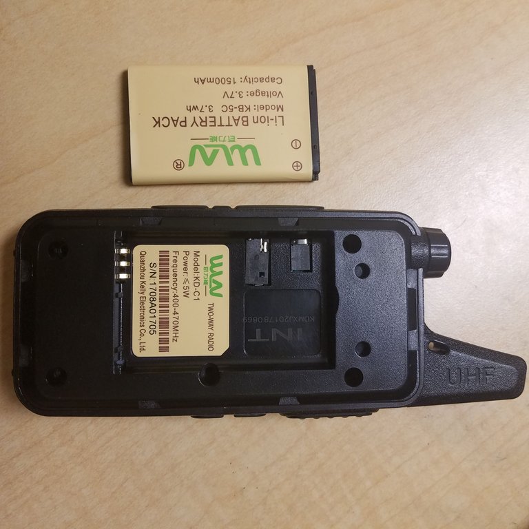
The battery is bigger than some cell phone batteries I've seen, and is apparently identical to some old removable Nokia phone batteries, although I can't confirm this. Either way, they're less than $10 to replace, so if you really needed to it would be quite easy to top up this radio without charging it.
The back plate is a thick piece of black plastic, and pretty much falls out once you've removed the fifth hidden screw. This reveals a large PCB which spans the entire body of the radio (they certainly didn't waste space):
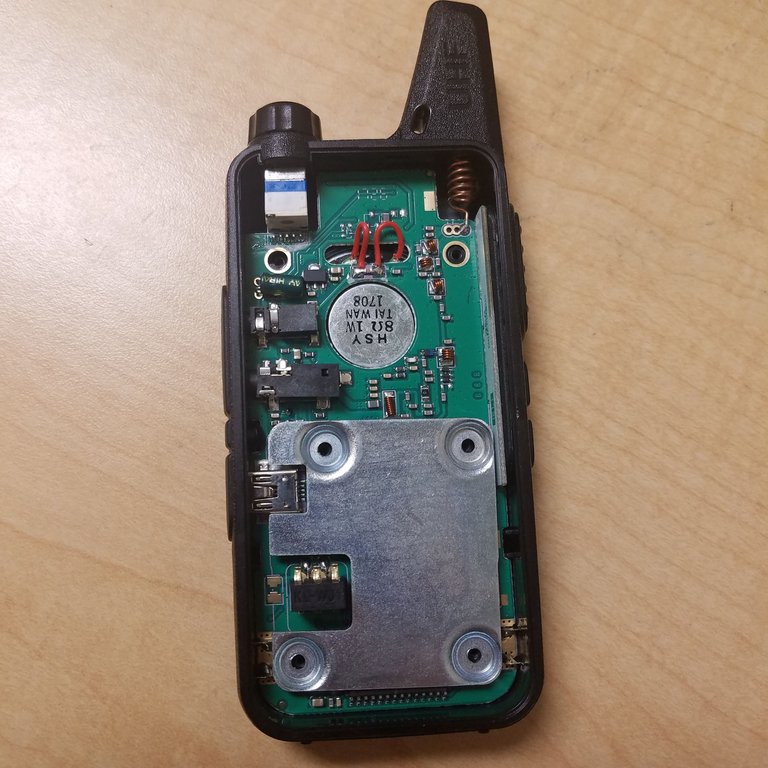
Quite a few parts are now visible. The two black boxes on the left are the audio and microphone ports. Above them can be seen a white and blue rectangle - a potentiometer, or variable resistor. This device controls the volume of the radio and turns it on/off. Turning it changes its resistance.
At the top left you can see a coil of wire (an inductor) leading to the short antenna. I assume this coil is to change the impedance of the antenna to match that of the receiver. Impedance is similar to resistance but for alternating current, and for inductors in particular, the impedance caused by the inductance doesn't lose any energy to heat like a resistor would (leftover resistance in the wire itself will still do this).
The silver circle in the center is a 8-ohm speaker. This speaker is much larger than it appears, and lies under a plastic grill on the front of the radio. I don't see a dedicated microphone (or a hole for it), so it seems that the speaker is serving both as a speaker and as a microphone. Any speaker can be used as a microphone, but often it ends up providing pretty bad sound quality when you talk into it. In this case, it doesn't seem too bad, as people can typically clearly hear me using this radio.
I'm not totally sure what the metal plate is for. It lies under the battery, but is separated by the plastic plate. I don't think it's to add weight like the metal block in the wireless mouse I previously wrote about, but it could be some sort of shield. Anyway, it comes right off.
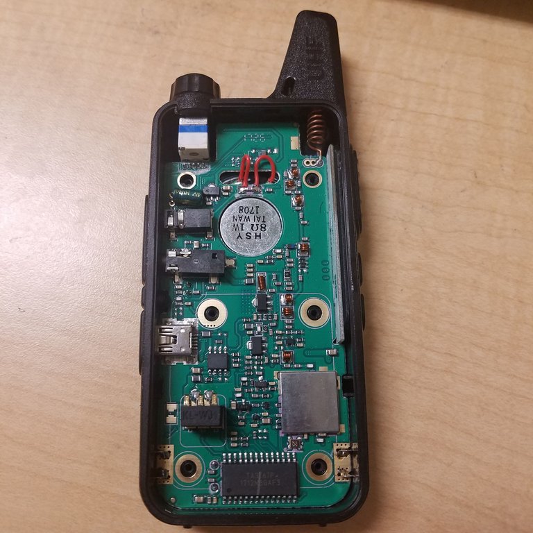
Removing the metal reveals a cluster of surface mount parts, mostly capacitors and resistors. You can also see a smaller, shielded region. Getting in here would seem to require destroying the shield, so I have avoided opening it up. A similar teardown I found elsewhere by someone who was wiling to damage his radio found that this shielded region contains a radio transceiver IC, responsible for receiving and transmitting signals.
The other side of the PCB doesn't contain much from what I've seen, and getting to it would require several rounds of desoldering and possible damage to the antenna, so I haven't risked it.
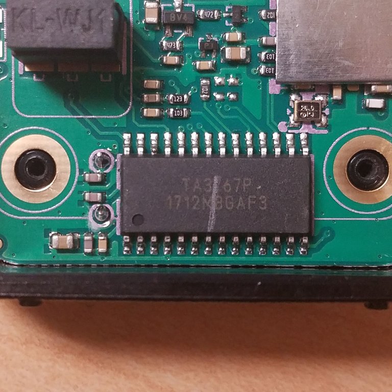
Above you can see what seems to be either a microcontroller or another supporting chip for the receiver. Unfortunately the part number did not return any datasheets (probably a no-name Chinese chip if I had to guess). If it's a microcontroller, it would control the channel selection and audio output (the radio speaks back the channel names to you). I believe there has to be some sort of microcontroller somewhere to control these functions, and this IC seems to be the most likely candidate.
Above and to the right of the potential microcontroller is a small crystal oscillator. These are devices that contain a piezoelectric crystal (something that vibrates when a signal is applied) used to oscillate at an extremely specific frequency. Also visible is a small PNP transistor near the top of the image, and the battery charging connectors.
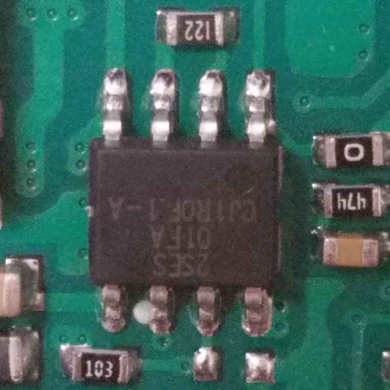
Here's another somewhat large IC I found above the charging terminals. Unfortunately I have once again come up empty in terms of datasheets, but I am pretty sure this is used as part of the charging circuitry for the lithium battery due to its proximity to the battery and charging port.
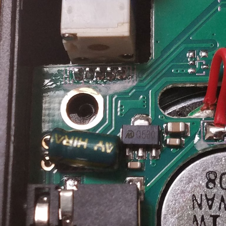
Here's a close up of the top-left region. The pins of the potentiometer are visible, along with a green capacitor and a semiconductor device labelled "Q500" (probably a transistor but I can't tell .. once again no datasheet).
As previously mentioned, getting deeper into the teardown would require at the very least desoldering, and possible damage to the radio. I quite like this radio since it's way more portable than my other handheld, so I am not too excited about damaging it and decided to hold off.
I'm a little disappointed by the general lack of identifiable parts, making identification a bit of a guessing game. This radio definitely wasn't made to be easily repaired or taken apart, but that's really alright for its price and complexity.
Let me know if you have any questions or comments, or if you'd like any other pictures/views of this radio.
Thanks for reading!
All images in this post are my own. You are welcome to use them with credit.
Being A SteemStem Member
I'm not surprised it works best with LTE 450 MHz, it is one of the most common frequencies in the Cellular IoT market. Thanks for sharing this, it was very interesting!
I read TA3767P for the microcontroller, I came up with nothing as well, although one of the 7's is not clear. Anyway another interesting teardown.
Unfortunately it seems that the manufacturer just used off-brand parts for everything, making it really difficult to figure out what any of them do.
Saya sudah membacanya. Walaupun sedikit yang saya pahami namun postingan ini sangat bagus. Menambah pengetahuan dan rasa cinta terhadap ilmu pengetahuan terutama sains. Banyak ilmu fisika didalamnya ada kapasitor, resistor, power dan sebagainya dalam konsep fisika ini. Semoga saya bisa hebat dan berhasil dalam menemukan eksperimen baru. Saya masih dalam proses memahami bahasa inggris. Maaf jika saya menulis ini dalam bentuk bahasa saya. Terimakasih.
That was interesting to see. Lately I've been exposed a bit more to electronics, before it intimidated me a bit I guess, but once studied it doesn't seem too hard to construct something little like a radio with a Rasberry Pi for example.
When I get back to uni, i'm going to try to make a photo diode detector to use in my masters thesis work. It's a good thing to have as a side skill, some electronics background i mean.
Cheers dude!
Great! If you make anything, be sure to post about it as I'd like to get into Pi projects more sometime and would love to see some other projects with the platform.
Do you mean a photodiode radiation detector or just a light detector? I have worked with photodiode radiation detectors in the past but have never actually gotten my personal one working. They are really useful tools since they can reliably detect gamma radiation without an irritating high voltage supply.
Yeah it is something i will surely start to learn when the time is right.
The photo detector will used to detect photons in and around the visible spectrum. I am hoping to use to it in the implementation of my Opto-Mechanics Physics Thesis.
I must detect the phase noise of a laser that has been mode cleaned by a filtering cavity. So I want to make a detector that minimises phase noise specifically, amplitude noise is not so important, but I must be able to detect phase noise with high sensitivity.
I hope that made some sense haha.
What about you my friend? What is your area of speciality?
Awesome, I'd love to see any such device that you end up building. I don't know a ton about lasers but your explanation makes sense.
Personally I'm still getting my undergraduate degree (physics and aerospace engineering), but I hope to go to graduate school for physics in the next few years. So I don't yet have a well defined specialization.
Just keep going, keep studying, working hard, even when it's a pain in the arse. Always believe in yourself, I didnt come from a great background, but with self belief and determination anything is possible man.
You'll find your favoured area and you will excel, keep doing your thing man.
If I can ever give you advice you know where to find me. I'm always happy to help good people.
Rock on dude!
Are you on discord? What's your user name?
Good information. Thanks to sharing.
I like.