In simple, turbo charger is a device used in internal combustion engines to to force more air inside combustion chamber to create more power, here compressor fan is used to suck air inside, as air goes through the compressor fan it compresses due to the fin design on the compressor fan.
.png)
Here I am showing you how I have designed a turbo fan for my custom turbocharger which I am making for my engine used in my buggy.
I have designed this compressor fan on SolidWorks-2016 because it has good user interface and smooth working with high quality graphics.
So let’s start....
.png)
.png)
First I making a 2D circle of required diameter then using EXTRUDE command I have extruded the circle to a thickness of 0.06in, thus I got a 3D thin plate.
.png)
.png)
Now making a 2D concentric circle of desired diameter for the shaft on the one face of the circle, then using EXTRUDE command I have extruded the circle to a straight path, thus I got a circular shaft
.png)
.png)
Now it’s time to make fins, for fins I have selected UPPER SURFACE of the circular base then made the 2D drawing as per calculated for the fin, using EXTRUDE command I have extruded the base of the fin, you can see in above picture.
.png)
.png)
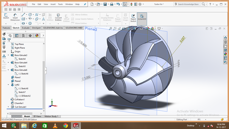
Now taking two planes PLANE 1 and PLANE 2 respectively, first plane is at the top of the extruded base of the fin and the second plane is 0.85in above it both planes are parallel to the circular base.
.png)
.png)
Now making a 2D drawing on PLANE 1 exact same as the cross-section of the above upper part of the extruded fin and making another 2D drawing on PLANE 2 as per design.
.png)
.png)
Now using SPLINE command making a 3D line joining one point of the 2D drawing at PLANE 1 to the same corresponding point on the plane 2.
Using LOFT command selecting the both 2D drawings and the line as the path, by lofting we finally get one fin.
.png)
Now using circular pattern command setting equal spaces between the fins and setting 8 number of fins using the circular shaft as the reference, thus i get my fins on the compressor fan.
.png)
Now using CHAMFER command cutting the outer edge of the cross-section of the shaft (this helps more air can enter in the compressor fan with less resistance) and making a hole through the haft using EXTRUDE CUT command and my TURBO FAN IS READY.
This is fascinating and insightful content. It really helped me understand the part operates!
Have you ever been to the Porsche Museum in Stuttgart? It's quite amazing.
Thank you my friend, no I never been to the Porsche museum, but will go definitely 👍
You are welcome.
Yeah check it out, it's pretty special. If engines are your thing then Stuttgart is a pretty good place for that. Both Mercedes and Porsche have their homes there. It's very german, the factories are right next to a football stadium! xD
Thank you for this great information, surely visit there.
@originalworks
To call @OriginalWorks, simply reply to any post with @originalworks or !originalworks in your message!
Wow! excellent and smart design.
Thank you my dear friend
well done !
Thank you my friend...
Really cool! That use of the chamfer command was pretty awesome to make the curves.
Thank you my friend...
These posts are really impressive @afzal-anees. You have a great command of the software. Hope to see some more of your buggy in action once you get to that point :)
Cheers - Carl
Thank you very much dear friend, yes I regularly posting as I am moving forward in my project.
Hope the final result will be amazing.