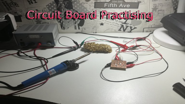
-- Thumbnail --
Hey there folks! :) I recently worked on a basic school project to prepare myself for a later exam that is lined up this year. I want to share my recent progress!
,,'kay then what did you do?"
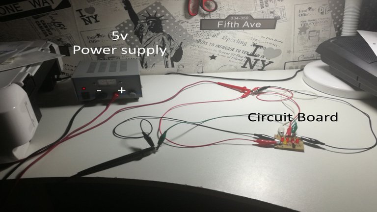
-- Picture 1 --
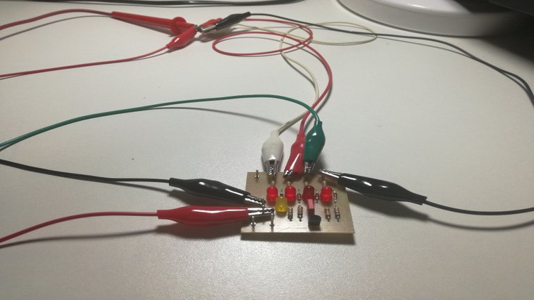
To put it simple, it is a self made circuit board which indicates the status of activated LED's.
-- Picture 2 --
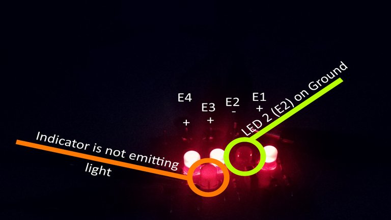
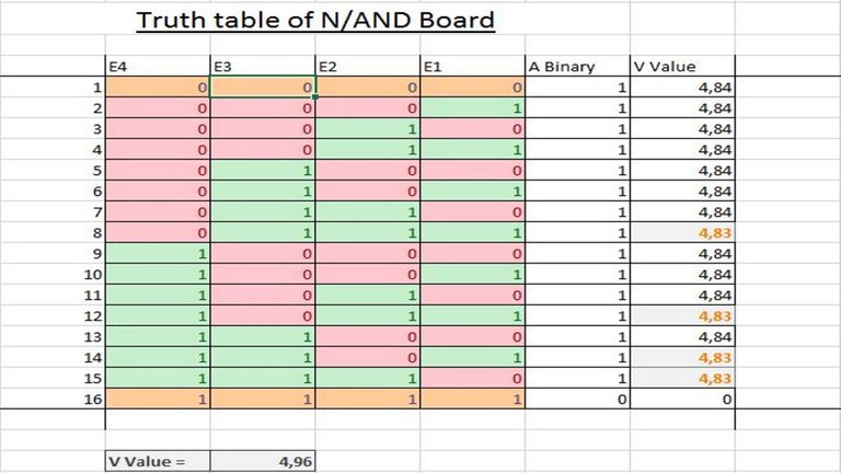
However it is working based on the Logic Gate N/AND. That means whenever 1 of my 4 LED's E1-E4 (Picture 2)
is connected to the Ground ( - ) pole the yellow LED A (I call it my indicator) should be emitting light.
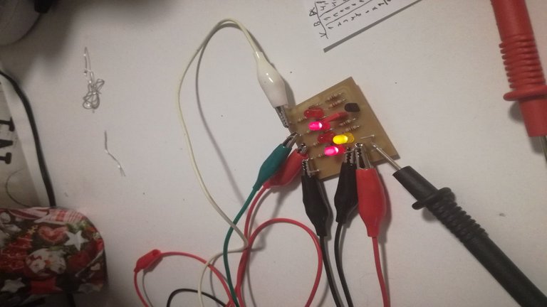
-- Picture 3 --
It was a really fun thing to do and I found out that I'm really not as good with the brazing and soldering as I used to. You might see how messy the board looks from its underside with all these scratches and solder stains.
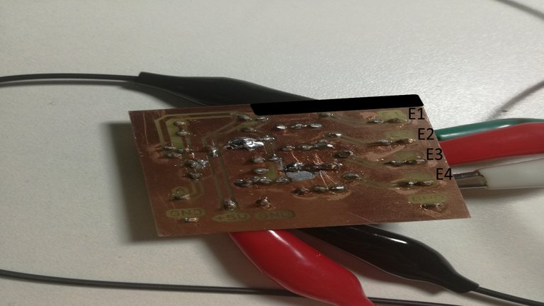
-- Picture 4 --
Then again it is nice to know because the project was just a warming up, so it is okay to make mistakes right ^_~ ?
Also the "debugging" was quite interesting because I had an error which prevented my indicator from emitting light while the second LED was connected to the ground and it took me ages to find what was wrong and it turns out that neither the connection lines between the LED were broken nor the path from the ground to the LED but instead the voltage regulator was pretty loose.
The error in bright so you can see the connections better
-- Picture 5 --
Now in dark so you can see the glowing better and also I labeled some parts
-- Picture 6 --
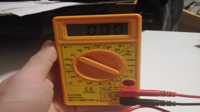
When I finished searching for errors and made sure that everything works the way it should it was time to measure the voltage throughout the whole board to make sure that this also works and I used this little helping measure device. :)
-- Picture 7 --
Very interesting my dude. Always been interested in soldering and how electronics work from the inside
Yeah me too but I still need to practice a lot more! :)
Wow. Looks like we have an electronics engineer in the making.