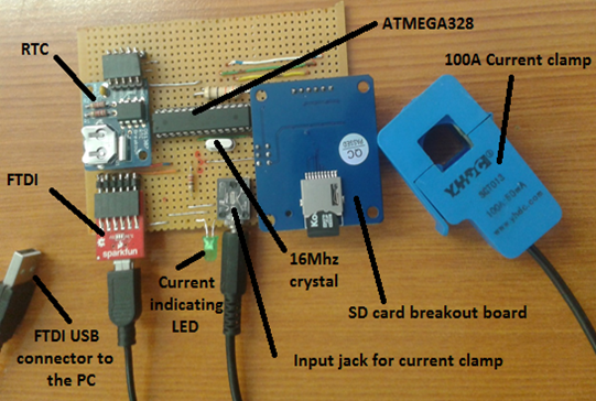
This is an UPDATE for My Arduino fun projects: Part1: Electricity data logging system
The update was request by @blocktrades to grow the “Arduino” tag on Steemit.
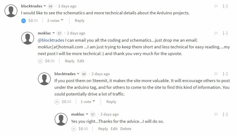
Comments can be found on my other blog (which will also be updated to include all the coding and schematics): My Arduino fun projects: Part2: Fingerprint scanner which enrolls and authenticate users then takes a picture and uploads it to Dropbox
I will breakdown the project into fewer parts and conclude by combining all the parts as a final design.
Parts to be discussed:
- ATMega328P-PU
- FTDI
- Real Time Clock (RTC)
- Current clamp
- SD card module for data logging.
- Final design
ATMega328P-PU
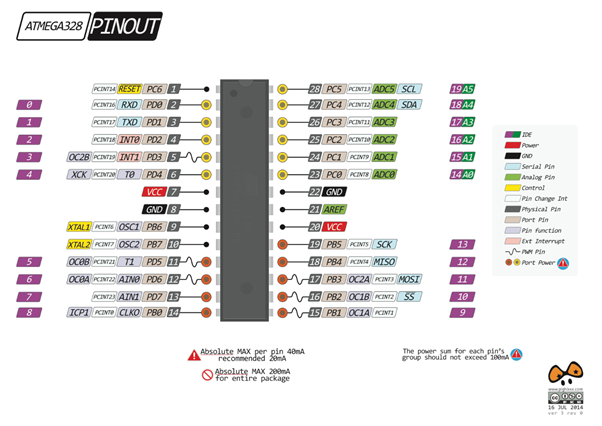
ATMega328P-PU to Arduino pinout.
ATMega328P-PU, a low-power version of the traditional ATMega328-PU was taken from an Arduino Uno with a pre-burned boot loader.
FTDI
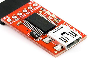
SparkFun FDTI breakout module.
FTDI uses an FT232RL IC to convert USB signals to UART signals (serial communication).
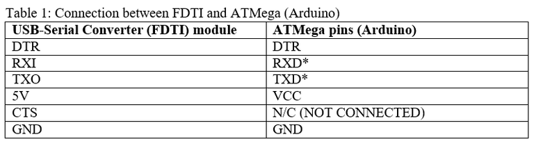
Wiring:

The above circuit can also be used to program the ATMega directly from Arduino IDE using the FTDI.
More information and drivers:
https://learn.sparkfun.com/tutorials/how-to-install-ftdi-drivers
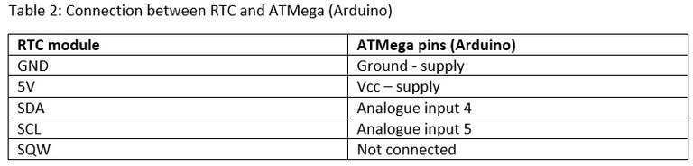
Real Time Clock (RTC)
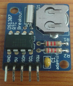
RTC breakout module
RTC is built around DS1307 IC with an external 32.768 kHz crystal and communicates with the ATMega (Arduino) through Inter-Integrated Circuit (I²C) protocol. RTC has a built-in power-sense circuit that detects power failures and automatically switches to the backup supply (coin battery) to continue keeping time.
Wiring:
Code:

Please note I have modified the example code to give me time and date as: day/month/year hour:minutes:seconds (e.g. 19/10/2016 14:00:00)
More information:
https://learn.adafruit.com/ds1307-real-time-clock-breakout-board-kit/overview
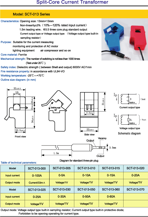
Current clamp

I used the YHDC SCT-013-000 with an input current: 100 A as seen below.
Wiring and operation:
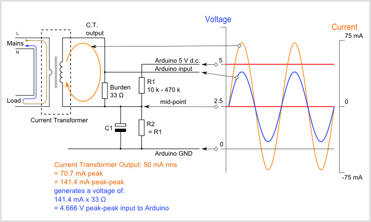
Image credit: openenergymonitor.org
Detailed operation and calculations are here
Code:
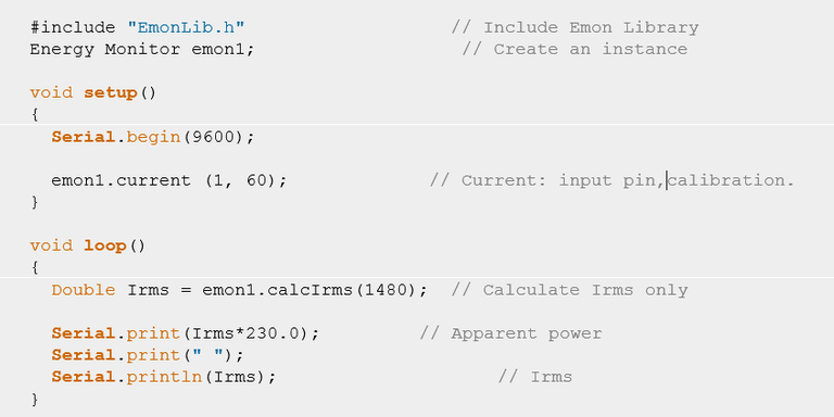
Please note in South Africa we use 220-230 VAC at 50-60 Hz, so kindly read operation and calculations to calibrate for correct readings.
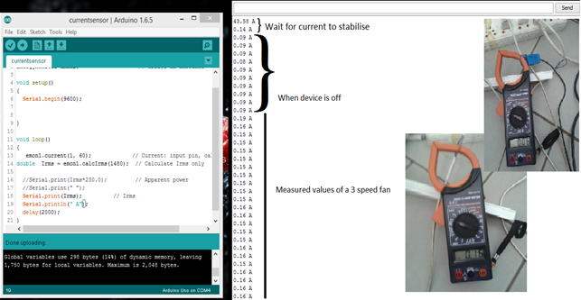
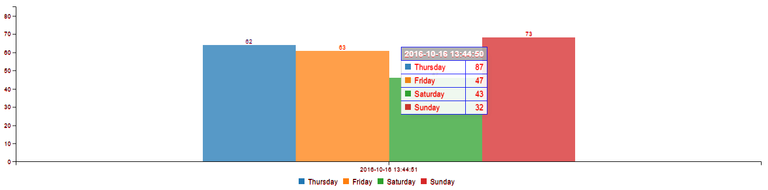
Results:
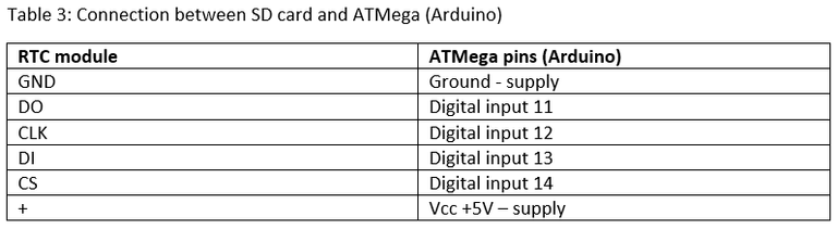
SD card
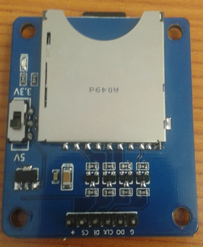
SD card breakout board
SD cards are popular for storing files and photos and widely used in almost every mobile device. SD card breakout board communicates with the ATMega (Arduino) through Serial Peripheral Interface (SPI) protocol.
Wiring:
Code:
The SD library comes with the Arduino IDE. It needs to be included at the beginning of the sketch.

Including `SD.h` automatically creates a global “SD” object which can be interacted within a similar manner to other standard global objects like “Serial”.
To “read” from SD card, first open the file:

It will return false if it fails to open the file, so check dataFile before using it. The “read” function reads the file line by line, so will have to use a while loop, until it fails to reach the end of the file.
To “Write” to SD card:
First open the file to write to with “FILE_WRITE” parameter.

The “open” function takes two parameters, file location and mode (only required for “Write”, if missing by default it opens the file in Read-Only mode).
It will return false if it fails to open the file, so check dataFile before using it and can write to the file using the following:
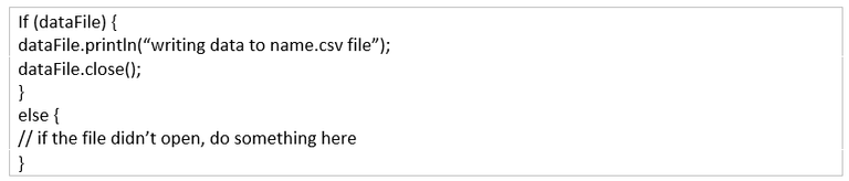
Close the file after writing to it and open one file at a time.
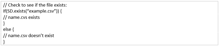
Check if a File Exists:
Create a Text/Excel File on SD Card:
There is not a function for this purposes, but you can open a file with “FILE_WRITE” mode to create a file, if this file does not exist.
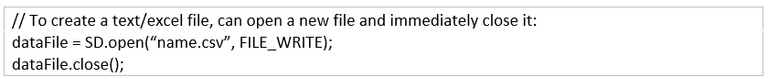
Please note name.csv its Excel file and name.txt its normal text file.

Final design
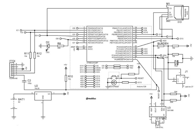
Final sketch:
Final coding is just combination of all the codes explained above. Note I do not discuss the LED blink rate and percentage change as they are optional but I have included them on the final sketch.
The full Arduino sketch is very long so I uploaded it on Github
Feel free to use it and have fun with it
Kindly upvote and follow me: @mokluc….I will upload another project soon: My Arduino fun projects
It's really interesting for me as I'm an engineer. Can you show some traces you made with it? What did you exactly constructed it for?
You don't quite directly state what it does ... Is this to create a log of how much electricity a given appliance burns?
My Arduino fun projects: Part1: Electricity data logging system "I was getting frustrated with wrongful billing by the municipality and decided it’s about time I kept a record of my electricity usage." So the idea was to be able to record my electricity usage on a daily basis for example:
@pery @fuzzytew: On the previous post:This post has been linked to from another place on Steem.
Learn more about and upvote to support linkback bot v0.5. Flag this comment if you don't want the bot to continue posting linkbacks for your posts.
Built by @ontofractal
Arduino looks like a lot of fun, I was checkout projects a litle while back and was thinking what a great learning experience it is... would love to play around with it one day.
It is very fun