What Will I Learn?
In this tutorial, readers:
- will learn advanced synthesis techniques on the software
- will learn how to use K-maps , truth tables more efficiently
- will be more familiar with logic circuit analysis
- will be able to construct any combinational logic circuit on the software
Requirements
In order to complete the tutorial, readers would have:
- Basic idea about logic designing
- Ability of reading a truth table
- Basic knowledge about K-maps
- a working PC, "Digital" software
Difficulty
- Intermediate
Tutorial Contents
In this tutorial, I am going to show synthesis techniques on the software which is called as "Digital". I will start the tutorial with explaining synthesis in digital circuits, and the reasons of using it, then I will explain the synthesis functions on the software, and will construct an example circuit to visualize it.
Episode 1: What is synthesis, and how can we use in digital circuit environment
Synthesis, often called as (logic synthesis in digital environment), is a technique to construct desired circuits, by giving the truth tables, K-maps or any input/output relation about it. Functions in softwares are generally able to construct circuits for the user who wants particular circuit designgs.
This method is widely used in digital desinging environment, since the circuits that we are facing today is very complex and have amount of gates & components that is very hard to calculate and analyze just by looking them. In this point, computers are ready to help us in terms of designing and observation, to learn whether the circuit functions properly or not.
In this tutorial, I will show those synthesis techniques on the software "Digital", and we will construct an example of circuit.
Episode 2: Synthesis function on Digital
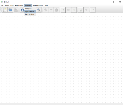
In order to reach synthesis function on the software, all we need to is find it from the top bar as shown below:
When it is clicked,following window will appear:
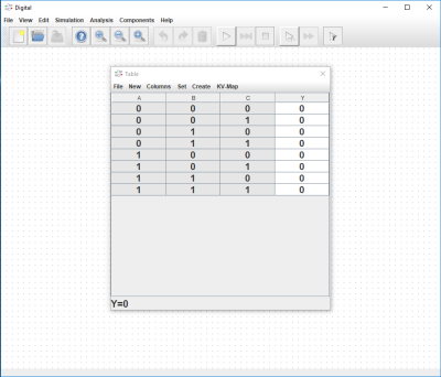
From here, we will be able to synthesize our desired circuit. Each tool on the top bar is be explained here:
File: From here we are able to Open or Save any synthesis design, and export it in LaTeX or HeX formats.
New: This is the tab that we add inputs and also choose the circuit type as Combinational or Sequential
Columns: This is the tab that we adjust Columns ( order and add/remove input/outputs)
Set: This tab is used to set the variables automatically
Create: This tab is ued to create circuit. User can create circuit by different gates & logic sequences as shown below:

KV-Map: This tab is used to obtain K-map output for the circuit.
Episode 3: Construction of a circuit by using Synthesis function on Digital
Here, I will construct a circuit to make the concept clearer. I will construct a circuit, whose logic behind it as states above:
4-input 2-output circuit. 1st output gives high when the number of 0's in input is even, whereas 2nd output gives high when the number of 1s in input is odd
Now we need to apply this logic to our sythesise function.I will explain the construction step-by-step.
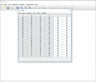
1- Adding 4 inputs / 2 outputs
To do this operation, we need to click Columns --> Add Input Variable and Add Output Variable until we have desired number of inputs/outputs.
2- Labeling inputs/outputs
Labeling operation can be done by right clicking on the desired input/output.
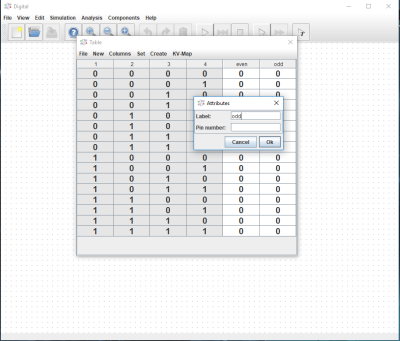
3- Filling the truth table
To accomplish this step, reader need to have enough logic knowledge. State that I have given above will guide us to fill the truth table. In order to change any value on the truth table, we just need to click it and change the number. For example in first line we have input as 0000, which means that number of 1's in output is 0 (which is even) and number of 0's of the output is 4(which is also even) so, we need to adjust:
output even to 1 and output odd to 0 as follows.
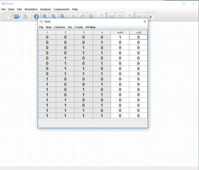
By using the same process, we need to fill the table. Resultant table should look like:
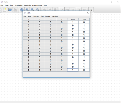
4- Creating the circuit
As a last step, we need to choose a way when creating the circuits as shown below.

I have selected Circuit option, and the result is:

So, we have managed to construct a 4-input/2-output circuit in a really short time, and did not waste any time in wiring.
5- (Optional) K-map visualization
User can also look into K-map of the corresponding circuit from KV-Map

Episode 4: Simulation of the circuit
Simulation results of the circuit is given below.
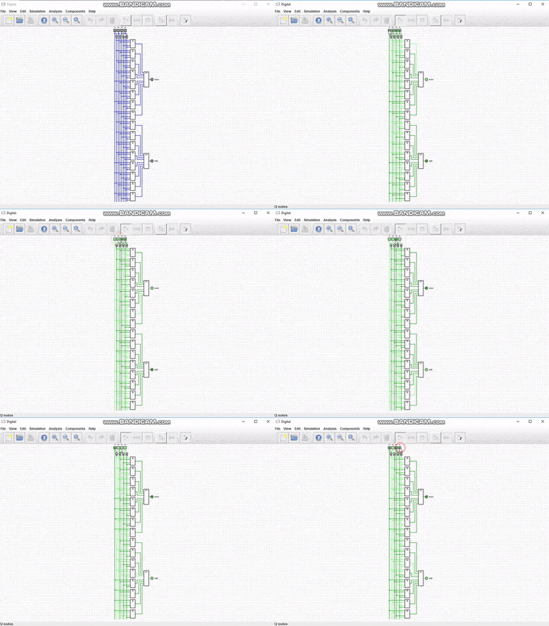
From here, we can see that the circuit works perfectly.
I have provided the files for this tutorial here. I highly recommend that the reader should work on the files that I have provided and try to understand the basics of the circuit & software. It will be benefical for he/she.
This is the end for this tutorial.Hope that you like it.
Digital is a really effective and easy to learn software, I highly recommend this software for the one who wants to make simulation in digital circuits especially. If you have any questions, please feel free to ask me on Discord (Escorn#4114)
Curriculum
I have provided the previous tutorials that I have prepared for the community:
| SimulIDE | Caneda | Digital | LogiJS |
|---|---|---|---|
| Part 1 | Part 1 | Part 1 | Part 1 |
| Part 2 | Part 2 | Part 2 | |
| Part 3 | Part 3 | Part 3 | |
| Part 4 | Part 4 | Part 4 | |
| - | Part 5 | Part 5 | |
| - | Part 6 | Part6 | |
| - | Part 7 | Part 7 | |
| - | - | Part 8 |
Posted on Utopian.io - Rewarding Open Source Contributors
Thank you for the contribution. It has been approved.
You can contact us on Discord.
[utopian-moderator]
Hey @escorn I am @utopian-io. I have just upvoted you!
Achievements
Community-Driven Witness!
I am the first and only Steem Community-Driven Witness. Participate on Discord. Lets GROW TOGETHER!
Up-vote this comment to grow my power and help Open Source contributions like this one. Want to chat? Join me on Discord https://discord.gg/Pc8HG9x
Congratulations! This post has been upvoted from the communal account, @minnowsupport, by Escorn from the Minnow Support Project. It's a witness project run by aggroed, ausbitbank, teamsteem, theprophet0, someguy123, neoxian, followbtcnews, and netuoso. The goal is to help Steemit grow by supporting Minnows. Please find us at the Peace, Abundance, and Liberty Network (PALnet) Discord Channel. It's a completely public and open space to all members of the Steemit community who voluntarily choose to be there.
If you would like to delegate to the Minnow Support Project you can do so by clicking on the following links: 50SP, 100SP, 250SP, 500SP, 1000SP, 5000SP.
Be sure to leave at least 50SP undelegated on your account.