Now that we have a high frequency, high voltage source the real fun starts.
The oscillator from the previous part incorporates our primary coil so we only need to add a secondary.
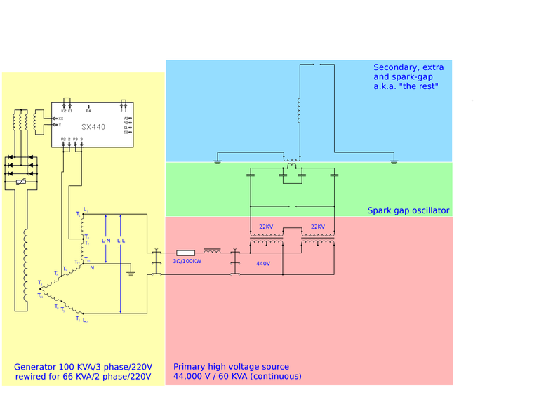
The design of our secondary is very straightforward. Tesla mentions on may occasions that the wirelength of this coil needs to be ¼ wavelength and it appears as though he assumes a velocity of c (speed of light). Again this is a point that can raise many discussions, but these can easily be circumvented by designing a coil such that the velocity factor equals 1.
That way we can all agree that our pulses travel through the coil at the speed of light, which btw is evidently not true, but it is funny that this way we can still agree on this.
OK, let me elaborate a bit on this. It is simply not true that pulses are travelling from one end of the coil to the other end, it is much more like a density wave. You can also compare it to waves on the water. A wave can travel from one end of the pond to the other while not a single molecule travels all that distance.
Having that out of the way, as I said, it is very easy to design such a coil. Namely there are 2 things you need to consider; the wire length (= ¼ wave = ¼ x speed of light / frequency) and the ratio of coil diameter / coil length (= Phi = golden ratio = 1.61803…). That is all, the entire design follows from these two quantities. To be honest, you still need to choose a suitable wire diameter, but how hard is that?
To find the frequency we simply measure the resonance frequency of the primary circuit.
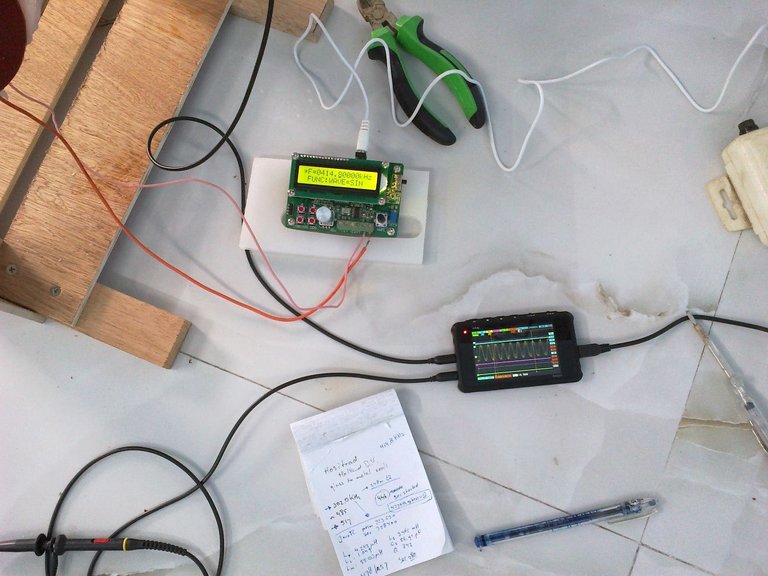
Following Tesla’s design rules we need to have the same amount of metal in the primary and secondary. The primary has 10 strands of 25 mm² in 1 single turn, so that is 250 mm².
So the secondary should have the same (if it were the same metal).
The secondary has 47 turns, so we need a wire size of little over 5 mm², if both were copper.
The primary however is made of copper and the (new) secondary is made of aluminium, which is less than half the weight of copper.
The old secondary used 6 mm² copper, the new one uses 10 mm² aluminium wire.
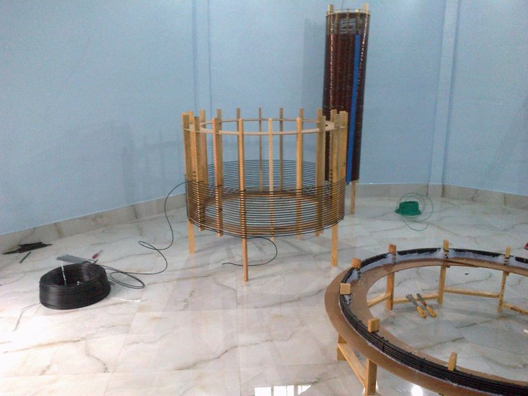
(the old secondary)
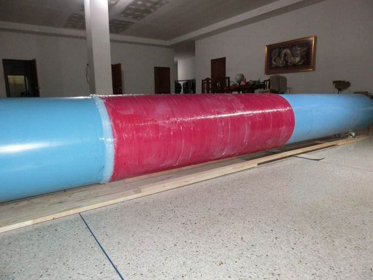
As you can see in the first picture the lower half of the coil is extra insulated and you may wonder why, as in the top half the voltages are much higher. This is true, but there are two things that we need to consider here. First, most of the voltage is generated in the lower half of the coil and for that reason the winding-to-winding voltage is much higher in the lower half.
But then we are just thinking of a smooth resonant action. This is not at all what is happening, which brings us to the second thing we need to consider; The primary, located at the bottom end of this coil delivers a very sudden and strong pulsed force onto the charges in the lower end of the secondary. So it takes a while for the elasticity of the charges to spread this force through the entire coil.
You can compare this to having a long metal bar. If you pick it up on one end it will rise evenly. But if you drop a large weight on one end the metal can not accommodate this suddenness and it will bend.
Due to this effect the wire-to-wire voltage is much higher in the bottom end of the secondary and therefore it is this part that requires extra insulation.
Some extra details on the construction
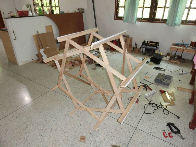
In the above picture you can see the frame. It is made of some light wood and it’s all glued together.
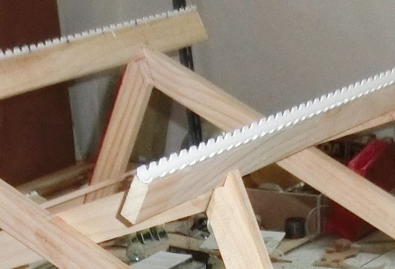
To hold the wires in place, I use a 15 mm PVC pipe, drill holes in it at the right distances and then cut the pipe across its length in two, giving two half-pipes with indents for holding the wire. This is glued onto the wooden frame.
Note that no metal is used as iron would affect the magnetic properties and other metals may cause sparks.
Here's a close up:
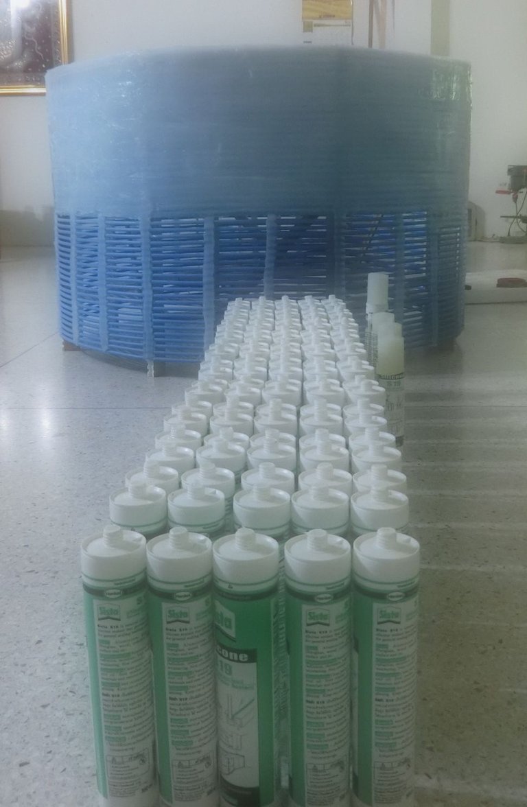
Well, next it is just a matter of silicone:
The “Extra” coil
The design of the “extra” coil is equally easy. We know the frequency and we know that we must now use half a wavelength wire. I also wanted the extra coil to have the same velocity factor which again dictates a length/width ratio (about 3.1). This ratio differs from the first because we have ½ a wavelength instead of ¼.
What makes it even more easy is that we can use 16” PVC as a frame for this coil.
This extra coil amplifies the voltage through resonance and through that we can achieve a few million volts. I have not measured its maximum nor the maximum spark length simply because it is not possible. I only have a few meters around the top.
From here we create sparks to the roof of the building. This roof is designed so that it collects its charge on the outer rim and does not spark back to the coil.
Also the roof can be electrically grounded and we can measure the current through this ground wire.
The idea is that the multi million volt spark will attract atmospheric electricity, so the current in this ground wire should be larger than the current in the ground wire of the secondary coil. Well, at least that is what we’d like to see…
Very soon.

We missed your posts my friend and we're waiting for new posts
Don't worry, I'll keep all of you informed of any progress.
Good... these are getting interesting.
Hello, can I translate this in French and steem the translation?
Sure! Assuming that your French is good enough ;)
(btw. please send me a link when you're done)
Since the original secondary (black) has been replaced (blue+silicone) the system was slightly detuned. Therefore a new element was introduced as can be seen here:
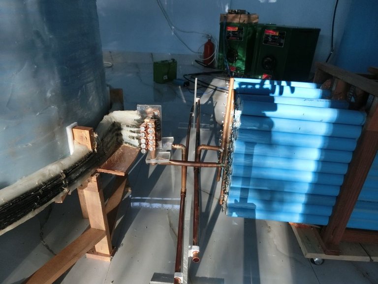
This adds a variable length of copper tube between the primary coil and the capacitors. The variable length means variable inductance, and this is used to tune te system.
More on all this later as soon as I have more time to post.
Oh, almost forgot to mention: everyone is free to copy and redistribute my work, but please add a reference to your source (my) material. I have invested a LOT of time and effort in this.
Thanks a lot :) ! French is my primary language so I guess it's good enough.
I will start from your first post on the tesla generator and send you the link in comment of the post translated.
And thank you too for helping spread clarity about Tesla's work!
If I can help in any way, just let me know.
such a great scientific work
Still waiting lol hope see your posts soon
Had some set backs (again) and I am working hard to solve the issues. Not much time to sit down and post...
But... it will come.... just not right now.... :)
a scientific paper is good and cool
A very fascinating report.
Also fascinating how much silicone you used... Do I count ~125 tubes there? Wow!
I am really enjoying your descriptions of your work, and as always I look forward to your next installment!
😄😇😄

Haven't seen you for some time. I have some new posts... ;) :)
THANK you for letting me know.
I shall check them out! :D
Thanks! Yes, I think your count is about right. The coil started out really light (light wood and aluminium coil) but ended quite heavy...
I guess I need to look at your whole series here to figure out what your goal is for this machine! I too am a Tesla Experimenter, but I am building a device of my own design. I call it the STG or "Simplified Tesla Generator" and I am hoping it will be an Over Unity Generator ;)
FOLLOW for You!
You may need to read the entire blog... Well, only the posts about Tesla.
Good luck with your STG. ;)
This statement here leads me to believe you are also building an overunity device! What you need in your ground wire is this:

Notice that the ground wire does not go directly to ground, it has a capacitor in it and you could replace the oscillator with an inverter. The capacitor should actually be a Cap Bank and the voltage can be a lot lower than the collected voltage, if you siphon it off with an inverter or other utilization circuit. But you already know these things :D
Thanks for your kind advice.
I take it that you have not read through my blog, yet. ;)
True! I need to do that...
Perhaps you could lend me some advice on my project.
I am doing it open source to protect myself.
The best advice I can give anyone who is doing some Tesla project is to read Tesla's lectures, articles, patents, notes and letters. All of it, and re-read it several times.
That is exactly what I have done, reading Tesla's own writings. Do you have a source or three for that? I've only found bits and pieces, but I am quite close to a full scale test.
Thank you I like your posts I'm follow you
http://www.americanradiohistory.com/Archive-Radio-Electronics/70s/1976/Radio-Electronics-1976-06.pdf
check out page 32. Have you heard about this guy? Interesting to see the article conclude the way it does... seeming to fixate on the plasma in air effects. Nice distraction ;)
Yes, I know him. Read about him and seen some video's on YT. His work deviated into (futile) nuclear fusion research. His coils ended up in the military (if I remember correctly) supposedly for airplane testing purposes.
Nice post..
Interesting that you note the extra coil to be 1/2 wavelength long vs 1/4 wavelength. I guess together that would produce a 3/4 wavelength system that would still have a voltage maximum at the top. In Richard Hull's Guide to the CO Springs Notebook, he states the primary and secondary can be a huge range....the important thing he notes is that the primary secondary can be highly coupled and acts as a high power signal generator. He feeds his primary and secondary into a 1/4 wavelength coil.
Really excited to see your results following the 1/4 -1/2 wavelength secondary and extra coil. Makes sense. Ive primarily used Richard Hull's advice and gone with a highly coupled primary & secondary to increase power into the system, but perhaps this type of system is missing something.....
Looking forward to the results!
I have always worked with 1/4 + 1/2 because that is what Tesla writes. It is easier if you follow Richard Hull's guide, but not better. If you have 1/4 wave in your extra coil, that means it has a high voltage on one end and a high current on the other end. Having a high current on the lower end of your extra coil means that you can not have 1/4 wave in your secondary coil. Thus you can not create a resonance rise in your secondary, and it will act as a normal transformer giving an output voltage based on the windings ratio. Therefore his setup is less effective in creating very high voltages, but it is a lot easier and it allows you to use a cheaper capacitor bank.
In a 1/4 - 1/2 setup you also have a tightly coupled primary-secondary which requires very precise tuning in order to get good results.
thanks you
Wow, I'm so excited to have found you. Tesla is my favorite scientist, a genius eclipsed by the interests of mediocre entrepreneurs. For me, the one who has contributed most to the studies on electricity. You are also the first person I find with publications related to my professional career. I am following you with pleasure and I will enjoy your publications. Thanks for sharing.
And it is a pleasure and honour having knowledgeable followers such as you. :)
informative news..
please master carry on your update.
i will wait for your next post...
Thank for upvote! Please follow me too!
What a brilliant mind. I wish I have a fraction of your brilliance. Keep up the good work. Best wishes!
please upvote got my new one who is a black shirt soldier ysng in the water yes,